Why Airgap Flux Density Drives Servo Motor Design Decisions
Motor designers rarely adjust airgap flux density in isolation, yet it influences nearly every aspect of permanent magnet brushless servo motor performance. It sets the foundation for torque production, efficiency and physical geometry, making it one of the most consequential parameters in magnetic circuit design. By modifying airgap flux density, a motor can be optimized for performance while reducing dependence on high-energy rare earth permanent magnet materials.
Those high-energy rare earth magnets have long enabled compact, high-output motors, but they also come with higher cost and growing supply constraints as certain rare earth elements become harder to source. As a result, many designs now rely on mid-range permanent magnet materials or combinations of magnet types to achieve magnetic properties that were previously unattainable with a single material. Examining airgap flux densities ranging from 3 KG to 9 KG shows how these choices impact overall servo motor performance.
The examples throughout this article will have the flux density of the iron laminations kept constant with the flux density of the iron in the lamination teeth kept at 14 KG and the flux density of the lamination back iron kept at 13 KG. This means that as the lamination iron thickness of the teeth and back iron will need to get larger as the flux density is increased to keep the flux density constant. This will cause the slot area for the wire to decrease as the flux levels in the air gap increase.
The effect of this is shown in Figure 1 below, with the diagram showing a motor with a low airgap flux density rating.
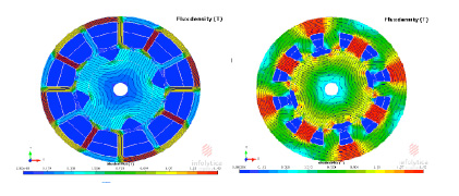
Figure 1 – Lamination Changes as Airgap Flux Density Changes
The diagram on the right shows a motor with a high airgap flux density with thick iron cross sections and a small area for the copper windings.
Linking Airgap Flux Density to Turns, Voltage and Resistance
When the stator diameter and stack length are held constant, the number of turns in the winding is directly related to the airgap flux density. This relationship can be shown using the standard equation for the voltage generated by a conductor moving through a magnetic field:
- Voltage equation: V = B × L × R × N
- Where V is voltage, B is airgap flux density, L is the airgap length, R is the airgap radius, and N is the number of conductors in the magnetic field
With the airgap length and radius fixed, increasing the airgap flux density requires a reduction in the number of turns to maintain the same generated voltage. As flux density increases, the available slot area for copper also decreases due to the increased iron cross section required to support the higher magnetic loading. Together, the reduction in turns and slot area influences stator resistance and, in turn, affects torque production and overall servo motor performance. These relationships are explored further in the examples that follow.
Using Motor Constant (Km) to Compare Servo Motor Performance
The motor performance can be measured in several ways for these comparisons. The most direct way is to measure and plot the motor constant which is defined as the motor torque constant divided by the square root of the stator resistance. If the top and bottom of this equation are multiplied by current then the equation would give the motor constant as the torque delivered by the motor divided by the square root of the power term I^2*R.
By playing around with these parameters of torque and dissipated power loss, it can be shown that the motor constant is affected by the airgap flux density and the amount of copper in the slots along with the motor stator OD, ID and length. Since the desired motor performance would be to get the most torque out of a motor with the lowest power loss, the Km will be at a maximum when the Kt value is high and the resistance is low.
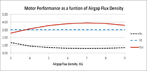
Figure 2 – Example of Motor performance as a function of airgap flux density
Why Maximum Performance Does Not Occur at Maximum Flux Density
Both the turns per coil and wire sizes are fixed whole numbers. This will cause the motor Kt to vary from the desired value and would skew the data. Here, we're using fractional values for the turns and wire sizes to keep the Kt a constant value at any value of airgap flux density. This will show the theoretical information for comparisons but would not represent actual values obtained in a true design. The comparisons done will plot the motor constant as a function of the airgap flux density. It shows that the maximum value of the motor constant is not always at the highest levels of air gap flux density.
The results of varying the airgap flux density in a permanent magnet brushless motor with the ratio of the OD to the ID of 0.6 is shown in Figure 2. As the airgap flux density is increased the resistance will start to drop but the lamination geometry due to keeping the lamination flux densities constant will override the decrease of the turns needed and the resistance will start rising again. It can be seen that the motor Km will start out increasing with the increase of airgap flux density and in some cases will decrease at the higher flux density levels. This shows that the best airgap flux density is not always the highest value that can be achieved with high energy magnets.
Effects of Stator OD to ID Ratio on Motor Constant
Another factor that affects the motor performance is the ratio of the stator OD to the stator ID. As this ratio changes, the effect on the motor constant will peak at different levels of the airgap flux density when the motor torque constant is kept at a constant value. This effect will first be shown on a motor with a stator OD of 3.6 inches and a stack length of 1.5 times the stator OD. The Torque constant in this example was kept constant at 3 Lb-In/A and the wire fill was kept constant at 40%. This was chosen because it would give a motor about 4 inches or 100 mm in diameter to run a 170 volt DC buss. This would be about an average size for a servo motor. The shaft diameter was small enough so that the rotor back iron would not be saturated at the highest level of the air gap flux density. This will keep the rotor geometry effects out of the example and keep the comparison to the airgap and stator.
Figure 3 shows the effect of the motor constant as the stator OD to ID ratio is varied from 0.5 to 0.65.
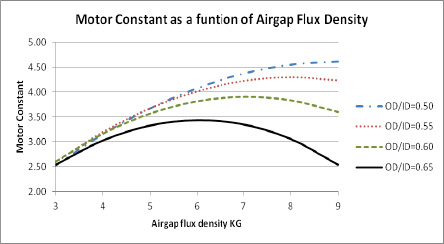
Figure 3 – 3.6 inch diameter cylindrical motor
In the OD to ID ratio of 0.5 the motor constant is increasing as the motor airgap flux density is increasing but is starting to flatten out at about 8 KG in the airgap. There is very little change in Km above 8 KG but there are significant changes below the 8 KG airgap flux density. If the OD to ID ratio is changed to 0.65 the motor constant will peak at a value of about 6 KG. At this OD to ID ratio, there is very little change in the motor constant from 5 KG to 7 KG but a large drop in the motor constant above and below these values. The other curves show different ratio values and show that the peak of the motor constant varies as the stator OD to ID ratio is changed. These plots show that the lower energy type magnet materials will work just as well as the high energy materials in designs made for the lower values and will be a lower cost material and will probably be a material that is more readily available.
Comparing Cylindrical Motors and Pancake Motors at Different Flux Levels
The first question that this may raise is, what will be the effect of the airgap flux density in a larger diameter thin ring torquer style motor? These motors are usually used as direct drive and have a lot lower speed requirements. This gives the motors a very high Ke and Kt values. The larger diameter and the low speed allows a higher pole count than the cylindrical motors. Since the diameter is large the motors would tend to have a lot higher OD to ID ratio than the cylindrical style brushless motors. The effects of the airgap flux density will be checked on a 14 inch diameter pancake motor with a 2 inch stack length and a 16 pole 48 slots magnetic circuit. The results of this are shown in Figure 3. This shows that for an OD to ID ratio of 0.7 the motor constant Km is still rising. As the OD to ID ratio is increased from the 0.7 ratio to a 0.85 ratio the motor constant starts to tail off and drop at the higher airgap flux density levels. For the OD to ID ratio of 0.85 the motor constant will peak at about 7 KG in the airgap. There is little change in the motor constant from the 6 KG to 8 KG level and any air gap flux density in this range would give about the same results. The motor constant shown in Figure 3 is in In-Lb/square root of ohms for units.
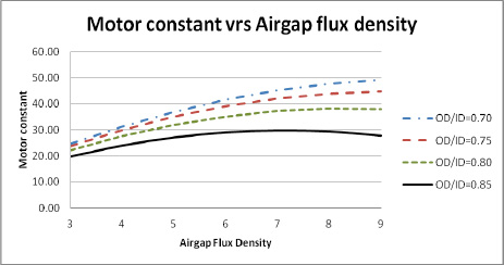
Figure 4 – 14 Inch OD Pancake Motor
Airgap Flux Density, Motor Volume and Magnet Material Tradeoffs
Another important consideration is how motor volume changes as airgap flux density increases. It’s well established that higher-energy rare earth permanent magnet materials enable smaller motor designs compared to lower-energy ferrite magnets. The goal here is to examine how airgap flux density influences motor volume when those material differences are taken into account.
To isolate this effect, motor volume is evaluated using a constant-diameter example in which length varies with airgap flux density. While volume could also be explored by changing diameter or by varying both diameter and length, holding diameter constant makes the overall trend easier to observe and compare.
The example used is a 4-pole, 12-slot motor with a 3.6-inch stator diameter. Several design parameters are held constant throughout the analysis:
- Torque constant (Kt): 3.3 lb-in/A
- Wire fill: 40 percent
- Rotor OD, rotor ID and magnet angle
- Winding: 26 turns per coil
Figure 4 shows how changes in stack length affect motor volume as airgap flux density varies from 3 KG to 9 KG. The data for this comparison was generated using motor design software. Common permanent magnet materials were selected to achieve airgap flux densities close to the target values, then magnet thickness and airgap thickness were adjusted to reach the required flux levels. Tooth width and stator back iron thickness were also modified to maintain a tooth flux density of 14 KG and a back iron flux density of 13 KG. Finally, motor length was adjusted to hold Ke constant at 39.5 volts per KRPM.
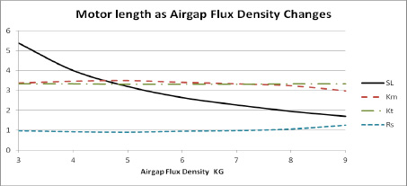
Figure 5 – Changing the stack length as the Bg changes
The results in figure 5 show that the motor Kt stayed constant as the flux density increased from 3 KG to 9 KG. The resistance took a slight dip initially as the airgap flux density increased but then started to rise as the stack length got shorter. The motor constant rose slightly as the resistance initially dropped, but then started dropping as the resistance started rising. The change in resistance in this example is due to the variation in stack length. This example has the same outer diameter in each case but the stack length is varying. The resistance due to the end turns will become a higher percentage of the total resistance as the stack length is shortened. This results in the slight increase of the resistance as the stack gets shorter. If the motor diameter had decreased with the shortening of the stack the Km and the resistance would have remained flat. The change in length shows a large decrease at the low airgap flux levels but tends to flatten out more at the higher airgap flux density levels. This shows the effect of motor volume decreasing with the increase of the airgap flux density.
Summary: Optimizing Airgap Flux Density for Servo Motor Performance
Airgap flux density is a primary design variable in permanent magnet servo motors, influencing both achievable torque and overall motor size. Rather than maximizing flux density, the results show that an optimum range exists where performance is balanced against geometric constraints in the stator.
That optimum depends strongly on motor geometry. Changes in the stator OD to ID ratio affect iron requirements, available slot area and winding turns as flux density increases, shifting the point of maximum motor constant. The preferred ratio varies by motor type, with thin ring torque motors and higher pole count designs favoring different geometries than smaller cylindrical motors.
These relationships are increasingly relevant as high-energy rare earth permanent magnet materials become more expensive and harder to source for motors. The ability to design around mid-range airgap flux densities, supported by evolving permanent magnet materials, gives motor designers greater flexibility in optimizing servo motor performance without relying solely on the highest-energy magnets.
For application-specific guidance on optimizing servo motor performance, connect with the engineering team at TruTech.