Lowell Christensen, VP Engineering
TruTech Specialty Motors
Magnetics 2014 Orlando Florida Jan 29 & 30, 2014
This presentation will discuss a case study comparing the design of an in-hub permanent magnet motor in a mobility cart used to move supplies from one location to another. This case study will compare using both an inner rotation and outer rotation permanent magnet brushless motors that are mounted inside a wheel that has an 8 inch maximum diameter. This cart will be a four-wheel cart with the motors in each wheel. The maximum load of the cart will be 1000 pounds and the maximum climb angle will be 5 degrees. The cart will have a maximum speed of 5 MPH. The motors will need to accelerate up to the 5 mph in less than a 5 second acceleration time. This case study will compare the magnet materials used in the designs and compare the construction differences of the two designs keeping the iron flux densities at 14 KG and varying the iron thicknesses as the airgap flux densities change. The three motors in this case study will be an inner rotation brushless motor using sintered Neodymium magnets and two outer rotation motors using bonded Neodymium magnets and Ferrite magnets.
This application is for a self-propelled cart using 4 wheels with an in-hub motor in each wheel. This will allow each motor to supply one fourth of the total load. Since this cart is self-propelled, it could be operated either autonomously or by someone operating the cart. The cart was designed to be a platform with the drive, controller and batteries in the base of the cart. The platform could have any type of shelving or equipment mounted on it making it a very universal type or cart. This cart was originally designed to move medical supplies and equipment but it could also be used in several other types of applications such as retail stores, warehouses or in factories. If the cart is used autonomously, it would need some kind of guidance system but these systems are readily available and would not be a problem for the cart. Most of the operation of the cart would be on a flat surface but it needs to be capable of climbing up a ramp to move from one level surface to another. This would include starting on the incline and accelerating to the rated speed on the incline. There are several ways to limit this peak load condition in the controller for the motors to limit the motor temperature to prevent overheating. In the case of this cart, the continuous torque rating of the motors will be rated at one fifth of the peak torque condition needed to start and accelerate on a 5 degree ramp. This case study will use a 24 volt battery system for the power source. The goal will be to keep the peak current under 25 amps.
This application will use a permanent magnet brushless motor. This type of motor will work very well in this application because the brushless motor is very easy to control by using feedback from the system. The speed and torque of the motor will be instantaneously monitored to operate smoothly under changing load conditions. This will allow the cart to be operated autonomously with systems to monitor the close environment of the cart to react to changes such as a person walking in the path of the unit. Other ways to operate the unit would be with someone walking alongside the unit with a hand held control. The Permanent magnet brushless motor will make these control options very easy to maintain. This application will have direct drive motors internal to the wheels. This will eliminate the need for gearing and eliminate the losses associated with gearing. With an 8 inch wheel outer diameter at a maximum cart speed of 5 MPH, the wheel speed will be a maximum of 250 RPM. This low RPM will allow the motor to have a large number of poles without raising the magnetic switching frequency in the iron to a large frequency that would raise the iron losses. The large number of poles will also reduce the length of the copper wire crossovers in the motor end turns. These two factors will reduce the motor losses and improve the system efficiency.
Since this motor will be operating off battery power in a low voltage type application, the resistance of the motor will be critical. The resistance will cause an IR drop that will reduce the voltage available to the motor to obtain the speed needed. A minimum resistance value can be calculated from the application parameters. This value can be compared to resistance values in the range from the minimum and maximum Ke and Kt values that the motor can achieve for this application. The motor speed of the direct drive wheel is very low so the voltage will not be a large problem and a battery power source will work well. The low speed will require a high Ke and Kt value at battery voltages so the current levels for the torque needed can be low. This low current will reduce the I2R losses and improve the efficiency of the system. Another factor to look at will be the number of poles and slots of the motor. If we use a slot pitch of one, we will minimize the resistance lost in the crossovers of the winding. Going to a large pole count will also allow us to pick a pole and slot combination that will give a high winding factor.
There are 3 types of permanent magnet brushless motors to consider for this application. One choice is an internal rotor motor with a separate wheel mounted to the shaft of the motor. The second choice would be an outer rotating rotor with the wheel mounted to the outer rotating rotor. The third choice would be an axial flux motor which would have the rotating part of the motor serving as the motor spokes of the wheel. The most conventional one would be the inner rotation type of permanent magnet brushless motor with the magnets mounted inside the airgap on a rotating rotor. Since the magnets are located inside the airgap in this design, this would have a low magnet volume and would allow a higher cost magnet material to be used. This higher cost magnet would also have a higher energy and could be a thinner material. This will also help keep the volume down and the magnet cost down. The outer rotation motor has the magnets located outside the airgap and would have a large magnet volume. This would require a lower cost material and this material would tend to have a lower energy material which also will need a thicker magnet. This will make the volume higher and require a lower cost magnet material. The third type of permanent magnet brushless motor would be the axial flux motor. This motor design has the airgap as a disk in the center of the motor with a disc of magnets on one side of the airgap and a disc of windings on the other side of the airgap. The winding of this style of motor would not contain any iron so the winding would also be considered part of the air gap. This will require a thick magnet to drive the magnetic flux thru the large airgap. The large airgap will also reduce the flux density in the airgap giving the need for a lot of turns in the winding. This would tend to make the resistance of this motor high and since the motor is running on battery power the resistance will need to be kept low. There are ways to add the iron to the winding which would lower the resistance but this would not be to lower the resistance to the value needed. This style of motor was eliminated first in consideration for this application due to the high resistance.
The motors chosen for this case study were 20 pole 18 slot motors. This was done to be able to wind the coils around a tooth to keep the end turns as short as possible. This combination also will give a winding constant of 94% so the motor efficiency will not suffer too much from the fractional winding. The inner rotation motor will have the rubber wheel is mounted to a wheel that is attached directly to the shaft. The winding will be on the outside of the airgap making the airgap radius about half the motor diameter. The average air gap radius chosen is 1.75 inches. The windings will be in a slot with a depth of 1 inch to keep the resistance low. Since the winding area is outside of the airgap, there will be a large slot area allowing heavy wire to be used keeping the resistance low. The magnet used will be a sintered Neodymium magnet grade of 48H.This will give a high air gap flux density keeping the number of turns low and the stator resistance low. The outer rotation motors will have the rubber portion of the wheel mounted directly to the outer rotor. This allows the motor to have a larger diameter and since the winding is inside the airgap, the airgap diameter was increased to 5.5 inches. This larger diameter will reduce the tangential force needed. This factor would either reduce the number of turns or reduce the amount of airgap flux density needed. In this case study, lower energy magnets with a lower residue flux density were used to try to reduce the cost of the higher volume of magnet material needed.
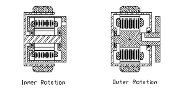
Figure 1 shows a basic inner rotation motor. The inner rotation motor in this case study is using N48H Sintered Neodymium magnets. The airgap diameter is 1.75 inches. The high energy magnets will help the number of turns low and having the winding outside the airgap which gives a large area for the winding and also a good thermal path for heat out of the motor. The large winding area will help to keep the resistance low. This design will have the wheel outside the outer diameter of the motor so the maximum diameter of the motor will need to fit inside the inner diameter of the wheel. This does give and advantage in that the clearance between the outer diameter of the rubber wheel and the housing of the motor will be large enough to clear most obstructions on the floor. Another advantage of the inner rotation motor is that the winding is connected to the outer diameter of the motor giving a larger area and a good transfer path for heat to exit the motor. The disadvantage of this design style is that the motor diameter will need to be smaller to fit inside the inside diameter of the wheel. Figure 2 shows a typical outer rotation motor. Two different designs of this motor were investigated. One used BN12H bonded Neodymium magnets and the other used M8H ferrite magnets. The outer rotation motor can have a larger diameter for the motor since the rubber portion of the wheel can be mounted directly to the outer diameter of the rotor. One disadvantage of this is that the rubber wheel will be wider or have small clearance between the outer diameter of the rubber and the outer diameter of the rotor. The outer rotation motor will have just the magnets and back iron outside of the airgap so the radius to the airgap will be larger than in an inner rotation motor. This larger radius will allow the tangential force to be smaller and allows the lower energy magnet material to be used. The airgap diameter used for the bonded neodymium magnet was 5.55 inches with a 0.2 thick magnet. The ferrite magnet needed to be thicker at 0.3 inches thick giving a 5.35 air gap diameter. The mechanical differences allowed the bonded neodymium magnet motor to have the same stator length as the inner rotation motor making the overall wheel size the same and still have a similar Torque constant and motor resistance. The ferrite motor has the same basic magnetic circuit as the bonded neodymium magnet but the stack length was increased until the motor had similar resistance with the same torque constant as the other two motors.
Table 1
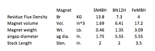
Table 1 shows the magnetic properties of the three designs investigated. The design with the SN48H is an inner rotation motor using sintered Neodymium grade N48H magnets. Since this design is an inner rotation design, the winding will be outside the airgap and the magnets will be inside the airgap. Also the magnet material will be a high energy material so the magnet thickness can be kept small. The magnets used here were 0.10 inch and were in motor with a 1.75 airgap diameter and a 2 inch stack length. This gave a magnet weight of 0.46 lbs. The next design using the Bonded Neodymium magnets was on outer rotation motor with the magnets located outside the airgap and the windings located inside the airgap. This gave a larger radius for the airgap which will reduce the tangential force required to get the torque needed. This reduced tangential force will allow a lower flux density at the airgap and will allow a lower energy and lower cost magnet to be used. The bonded neodymium magnet material was used because it would give a similar performance to the sintered neodymium magnet motor in the same length stack and the basic motor size. The air gap diameter grew from the 1.75 for the inner rotation motor to 5.55 inches for the outer rotation motor. Also the lower energy magnet material needed a thicker magnet to be used. In this example the thickness was increased to 0.20 inches thick. These changes increased the magnet volume but the magnet material has a lower density so the total magnet weight for this design is 1.53 pounds. The third case was to use Ferrite magnets in the outer rotation motor. These magnets have a lot lower cost but also have a lot less energy. The stack length had to be changed to 3.5 inches to get similar performance out of the motor. Also the magnet had to be thickened to 0.30 inches for this design. This gives an airgap diameter of 5.35 and increases the volume to 17.2 inches cubed. The ferrite magnet also has a lower density so the total magnet weight will be 3.5 pounds. This is a lot higher weight than the Neodymium based magnet but it also has a lot less cost so the motor would be attractive if the larger motor length is not a problem.
Table 2
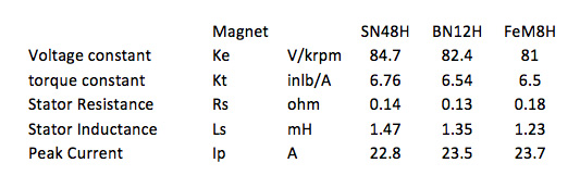
Table 2 gives a performance comparison of the three designs. The direct drive of the motors incorporated in the wheels will give a low speed of the motors and require a high value for the Ke and Kt. The high value of the Kt will keep the current levels low. The Ke value picked was between 80 and 85 volts per KRPM. The input power can be a 24 volt battery source with a capability of a 25 amp trapezoidal drive. The resistances of the three motors were kept very similar and vary from 0.13 to 0.18 ohms with the ferrite magnet motor having the highest resistance. The inductances of the three motors were also very close and a value above 1 mH so the current ripple will not be a problem. The peak currents are all below the 25 amp maximum so the cart will be able to start and accelerate up the 5 degree incline. This table shows that all of the designs will work in this application and the only differences are in the construction of the motors and in the weight of the magnet materials. The two motor designs using the Neodymium based magnets are very similar in size but the Ferrite magnet motor will be a lot longer. The motor performance parameters are all very close as shown in Table 2. The main difference will be in the cost of the magnets for the motors. The outer rotation motor using bonded Neodymium magnets will have 3 times the magnet weight of the inner rotation motor using Sintered Neodymium magnets. The outer rotation motor using the Ferrite magnets will have 7 times the magnet weight of the inner rotation motor using the Sintered Neodymium magnets.
Summary and Conclusions
Three permanent magnet motors were designed to meet a specification for a self-propelled cart using an in-hub direct drive permanent magnet servo motor. These designs used different permanent magnet materials and compared the motor size and performance of a sintered Neodymium, a bonded Neodymium and a ferrite magnet material. This case study showed that the equivalent motors could be made from the 3 magnet materials. The performance of the motors was essentially the same but the motor designs and weight were different. The inner rotation would be the most conventional design and the easiest to fit into the cart wheels. The separate wheel can be the same length as the rubber surface used for the wheel and does not have clearance problems for items on the floor surface. The outer rotation motors would have the rubber portion of the wheel attached directly to the rotating outer rotor but this will give a longer rotor portion of the wheel and create problems with the clearance between the rotor and the floor if the rubber portion does not cover the entire rotor. The ferrite magnet version was longer and makes this clearance issue a bigger problem. The other problem would be in the magnet costs. The weight difference of the inner rotation Sintered Neo magnet motor to the outer rotation magnet motor gives three times the magnet weight which would keep the magnet costs similar. The Ferrite magnet outer rotation motor was longer in length and had about 7 times the magnet weight but the magnet material is significantly less cost and would be the cheaper motor to build. The easiest motor to fit into the wheel would be the inner rotation motor using the sintered Neodymium magnet. This motor would still be the recommended design unless the lower cost of the ferrite motor would override the problem of the heavier motor with the small clearance between the motor rotor and the floor surface.