As engine driven hydraulic and pneumatic applications migrate to electric motion, the concept of designing the entire system to meet mission requirements becomes important. Using recent developments in 1 to 10Kw power conversion, it is now possible to design the motion system to the optimum operating voltage for the application and select the power source to support the mission energy requirement, even if that source is a different or varying voltage source. This presentation will explore the concept of off grid mission focused electric motion using examples from commerce, industry and agriculture.
Challenges of Off Grid Auxiliary Motion
Off grid auxiliary motion encompasses all motion applications under 10Kw not directly connected to the utility grid, except traction. Besides including applications that are handled today by a power take off shaft or battery power, this definition also includes applications that are handled today by small internal combustion engines (ICE).
Some examples of off grid auxiliary motion are;
- Lift gates, winches, and closed circuit or engine pump driven hydraulics on ground transport equipment.
- Marine winches, auxiliary propulsion and pumping.
- Generator driven or pneumatic driven tools.
- Small ICE driven agricultural equipment.
All off grid auxiliary motion applications face the challenges of a difficult environment and the quest for improved efficiency, but recently additional requirements have emerged such as increased operational time. For example, new configurations of delivery trucks may have multiple lift gates or more frequent stops delivering higher loads. Other relatively new requirements are the “carrot” of reducing fuel use to save money and the “stick” of environmental requirements limiting emissions from small IC engines, or requirements eliminating the engine entirely in the case of two cycle ICE’s.
The Mission Methodology
Recent advances in motors, power electronics, battery technology, controls and vehicular electronic packaging have opened the door to re-evaluating off grid auxiliary motion applications with a “clean sheet” approach. While relatively uncommon to traditional commercial and industrial applications, a “clean sheet” approach has been used for some time in aerospace and military spheres where it typically focuses on the mission the application is used in with an eye to maximizing the success of that mission. Mission definition and requirements are defined first, then an implementation is fleshed out.
For example, aerospace had long sought a solution to the heavy, high maintenance mechanical systems used to control flight surfaces on aircraft. In a classic case of a “clean sheet” design, this led to the first pure electronic fly by wire aircraft which was the Apollo Lunar Landing Research Vehicle in 1964. Today most military and many newer commercial aircraft are fly-by-wire. By rethinking the problem from a mission viewpoint, the designers could not only meet the requirements of the previous approach but add redundancy and functionality not previously possible.
There are three steps in realizing the Mission Methodology
- Define mission Requirements
- Model the mission
- Synthesize the mission solution
Defining the mission requirements involve defining the task and environmental constraints, without pre defining the components or even the process for achieving the mission. For instance, the requirements may be “move a 600 lb object from Y = 10000 ft to Y = 10300 ft X at a rate of 150 feet/ second in -20F ambient temperature”. The requirements may include trade off variables, such as “as power efficient as possible” or “as light as possible”. All these qualifiers put a box around the mission, without defining implementation details.
The next step is modeling the mission. Here we have many tools to accurately model the mission such as Simulink, Mathcad, and Xcos. Once the overall mission is modeled accurately, mission parameters are exercised to determine worse case scenarios and determine any additional overall mission requirements. The model is then expanded to include generic “black boxes” representing the energy source and power conversion blocks and exercised again to determine the implied requirements of each.
The third step is synthesizing the mission solution. Using the mission model from step two, the designer further expands the model and fills in the details of each of the “black boxes” or components. Since this is a “clean sheet” process, the designer is free to explore the broad spectrum of solutions for each component as well as solutions that may synthesize combinations of components. As we will see, this may lead to defining previously unrealized but very practical building blocks.
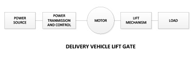
Design Example/ Delivery Vehicle Lift Gate
The first step is to define the mission requirements. We will use a delivery vehicle lift gate as our example application. The lift gate as a 1000 lb capacity and is welded to the rear of a standard 53 foot over the road trailer.
First we describe our mission requirements;
- Maximum load. This is the maximum capacity of our lift gate, in pounds. For this example we will use 1000 lbs, which is common for a medium lift gate.
- Maximum velocity. This is the maximum velocity of the lift, in feet/ second required to maintain a safe lift. In our example we will use .5 ft/ second.
- Maximum acceleration. This is the maximum acceleration that can safely be applied to the load. We will use .5 ft/sec**2, which is a very gentle 1.5% of gravity but will accelerate our load to maximum velocity in about a second.
- This is the distance of the lift, in feet.
- Power Source. The vehicle’s engine is the primary power source for the lift gate, however environmental constraints and fuel cost prevent running the engine while operating the lift. Therefore the actual lift power source must be a secondary storage element such as a rechargeable battery.
Lift mechanism and Load Model
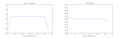
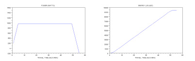
Scilab was then used to model the lift gate mechanism and load, providing velocity, force, power and energy profiles of the lift mission. At this point, out model consists of the lift gate from the load back to the motor shaft and includes the mechanical transmission. Transmissions can vary in efficiency, so we used a moderate 70% in our model. The results of the Delivery Lift Gate mission model are shown below.
We can now detail the requirements for the remaining system blocks.
Motor and Power Transmission and Control
From a system standpoint, we are interested in the efficiency from the power source to the motor shaft, in particular, the worst case efficiency. This will dictate how many full capacity lifts can be achieved before depleting the battery to the maximum allowable level. We will assign a minimum efficiency of motor and power transmission/ 50% to account for losses in power distribution and the motor. From our model we see that the peak shaft power required is 960 watts and the total energy for a lift is 9500 joules. Applying the 50% minimum efficiency, we have an input requirement of 1920 watts peak and 19000 joules per lift. We also add the environmental requirements of the over the road environment and a requirements for minimal added weight, minimum maintenance and high reliability. Since system efficiency translates into lower operating costs, we can add a preference for higher efficiency solutions.
Power Source
Our power source must be capable of providing the 1920 watts peak power and 19000 joules per lift energy requirement. We have already established that this power source must be a secondary storage element such as a rechargeable battery. Additional operational requirements of the power source would be to allow a minimum number of lifts per mission; a minimum time between missions for recharge; minimal added weight; minimum maintenance and high reliability.
Synthesizing the Lift Gate Mission Solution
Now that we have established the requirements for the Vehicle lift gate, we can focus on the implementation solution. There are a variety of configurations the system from the battery to the motor shaft can take.
The conceptually simplest configuration is a 12VDC brush motor, a length (in this case about 116 feet) of #2 AWG cable and the vehicle’s 12V lead acid storage battery. The control could be a simple switch operated solenoid contactor.
Assuming a brush motor with an efficiency of about 70% at full load, a cable resistance of .018 ohms (116 feet of #2 AWG), a fully charged battery voltage of 13.5 volts and a motor shaft load of 960 watts, we can calculate the available motor voltage, battery current, battery power and system battery to shaft efficiency for this configuration.
| SHAFT POWER | 960 | WATTS |
| MOTOR EFFECIENCY | 0.7 | |
| BATTERY VOLTAGE |
13.48457649 | VOLTS |
| CABLE RESISTANCE |
0.018 | OHMS |
| MOTOR POWER | 1371.428571 | WATTS |
| MOTOR VOLTAGE |
11.3 | VOLTS |
| CURRENT | 121.3653603 | AMPS |
| CABLE LOSS |
265.1319123 | WATTS |
| BATTERY POWER |
1636.560484 | WATTS |
| BATTERY TO SHAFT EFFECIENCY |
0.586596102 |
Under these conditions, the conventional brush motor configuration has an overall efficiency from power source to motor shaft of 58% which meets our minimal efficiency requirement of 50%.
An alternative configuration in common use is to add a separate lead acid battery, located near the lift. This can reduce the battery to motor cable length to as little as 10 feet and resistance to as little as 1.55 mOhm increasing power source to motor shaft efficiency to 69%, or close to the motor only. The down side of this approach, besides the costs, space and weight associated with the auxiliary battery, is the need to recharge it between missions through a cable running back to the vehicle battery. Often a DCDC booster/ charger is added to this circuit to maintain proper charging of the auxiliary battery. However, on an urban delivery truck the charge time between missions may be short and the recharging of the remote battery may be problematic.
| SHAFT POWER | 960 | WATTS |
| MOTOR EFFECIENCY | 0.7 | |
| BATTERY VOLTAGE |
13.45982814 | VOLTS |
| CABLE RESISTANCE |
0.00155 | OHMS |
| MOTOR POWER | 1371.428571 | WATTS |
| MOTOR VOLTAGE |
13.3 | VOLTS |
| CURRENT | 103.1149302 | AMPS |
| CABLE LOSS |
16.48066768 | WATTS |
| BATTERY POWER |
1387.909239 | WATTS |
| BATTERY TO SHAFT EFFECIENCY |
0.691687881 |
Introducing the DCDC Transformer
Physics limits practical integral horsepower low voltage DC motors to relatively low speeds of 3000 RPM or less. Also, DC brush motor speed can drop 25% or more from no load to full load and efficiency rarely exceeds 70%. Increasing motor speed improves motor power density, speed / torque performance and efficiency but increasing motor speed at low input voltages results in very low inductance motors, significantly increasing control complexity. By increasing the motor supply voltage and incorporating a motor controller at the motor, we can allow motor inductance to remain high enough to use the conventional PWM modulation used in modern grid operated motor controllers. Also, since motor controller cost, weight and size are dominated by the current level that needs to be handled, raising the supply voltage reduces the current by an order of magnitude or more. In some cases, raising the voltage to grid levels would allow the use of inexpensive conventional AC induction motors. The first stage in a grid operated motor controller is to convert the utility AC into high voltage DC. We can convert the low voltage battery power at the battery to high voltage DC, then distribute it to a motor controller/ motor located on the lift gate.
The advantage of running motors on higher voltage was, of course, the killer app for Nikola Tesla 125 years ago. Today we can realize the building block that his competitor, Edison, needed but could only dream of; the DCDC Transformer.
The DCDC Transformer is not a DCDC converter. The primary function of the DCDC Transformer is to convert a low DC voltage to a higher DC voltage at maximum efficiency. Since the equipment downstream (motor controllers etc.) perform their own regulation functions, it’s not necessary for the DCDC Transformer to regulate the output voltage like its DCDC converter cousin. This lowers the cost, size and complexity of the DCDC Transformer, particularly at power levels above 1kw. Techniques such as high frequency fully resonant conversion and software control reduce switching losses in the DCDC Transformer to near zero. Taking advantage of recent advances in low MOSFET on resistance and planar magnetics reduce conduction losses to a minimum and creates a platform where further devices improvements can be easily incorporated.
The unregulated DCDC Transformer has the following properties
- Unregulated high power output (scalable from 1 to 10kw)
- Very high efficiency (95% or greater)
- High power density
- High degree of protection
- Telematics capability
For example, by incorporating a 1:30 DCDC Transformer at the battery, the distribution voltage is boosted from a nominal 12 VDC to 360 VDC allowing a number of system improvements for the lift gate;
- Full load distribution current drops from 120 amps to 4 amps, allowing the use of #12 AWG wire and reducing distribution losses by 90%, without an auxiliary battery/ charger.
- Motor speeds can be 10000 RPM or higher allowing substantially smaller motors.
- The use of brushless, synchronous and induction motors with much greater speed/ torque operating area becomes practical.
- A motor mounted controller provides control resolution and operational functions not previously possible.
- Telematics on the DCDC Transformer and the motor controller provide monitoring and safety functions not previously possible.
- Distributed systems such as multiple lift gates, multiple axis, auxiliary chargers and remote actuators become practical.
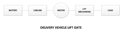
Applying the DCDC Transformer to the Delivery Vehicle Lift Gate
We can revise the implementation solution of our Delivery Vehicle Lift Gate to include the DCDC Transformer and a motor controller, as well as change the motor to a high speed, high efficiency brushless motor.
Looking at each component;
- Battery; The battery is the same as in the previous model
- DCDC Transformer: We will use a 1:30 DCDC Transformer in our model with an efficiency of 95%.
- Cabling: Cabling is 116 ft of #12 AWG wire.
- Motor Controller: The motor controller is a motor mounted BLDC drive operating at 90% efficiency.
- Motor: The motor is a BLDC motor capable of 10000 RPM and 85% efficiency.
The addition of the DCDC transformer and motor controller results in an 85% efficiency (90% x 95%) on energy transmission from the battery to the motor. The much smaller distribution current through the #12 AWG cabling dissipates a negligible 4.3 watts.
| SHAFT POWER | 960 | WATTS |
| MOTOR EFFECIENCY | 0.85 | |
| BATTERY VOLTAGE |
13.5 | VOLTS |
| CABLE RESISTANCE |
0.45 | OHMS |
| DCDC XFMR RATIO | 30 | |
| CONTROLLER EFFECIENCY | 0.9 | |
| DCDC XFMR EFFECIENCY | 0.95 | |
| BUS VOLTAGE | 405 | |
| MOTOR POWER | 1129.411765 | WATTS |
| CONTROLLER POWER | 1254.901961 | |
| BUS CURRENT | 3.09852336 | AMPS |
| CABLE LOSS |
4.320381156 | WATTS |
| BATTERY POWER |
1325.497202 | WATTS |
| BATTERY TO SHAFT EFFECIENCY |
0.724256527 |
Overall battery to shaft efficiency is 72.6%. This is 24% higher than the simple direct connection configuration. The lift gate can perform 24% more full load operations on the same battery energy.
There is a smaller efficiency advantage for the DCDC Transformer approach compared to the alternative approach of locating a second battery at the lift gate. However there are the operational advantages that come with the DCDC Transformer such as no second battery to maintain. Functions such as tight lift speed control, battery energy monitoring and even remote wireless operation become possible. Also, the lower weight of the DCDC Transformer configuration translates into fuel savings, particularly for an urban delivery truck.
Other off grid applications
Using the Mission Methodology, many off grid hydraulic, pneumatic and even small internal combustion engine applications can be reexamined and improved. Better efficiency, added functionality, more flexibility and improved system management become possible.
By incorporating the DCDC Transformer, power source voltage and motor operating voltage become decoupled, permitting the system designer to size each to the mission. Battery banks can operate at the optimum voltage for the chemistry involved or to accommodate low voltage charging technologies such as solar cells. The motion axis can operate at a different voltage optimized for power distribution and motor design. The DCDC Transformer extends the Mission Methodology to previously impossible intermittent integral horsepower applications and enables distributed high voltage DC to new off grid multi axis applications. Just a few candidates are;
- Utility bucket trucks
- Winches or multi winch systems, both vehicle and marine.
- Solar powered grain augers, pumps and other agricultural applications.
- Generator replacement or augmentation in food trucks and first responder units.
- Indoor off grid construction and material handling
- Grounds keeping, replacing small gas engines in leaf blowers and mowers.
- Alternate energy systems with low voltage storage and integral HP applications.