Article for Machine Design Magazine
Lowell Christensen, Founder and VP of Engineering
TruTech Specialty Motors
Motors that are built into the hub of a wheel can offer many advantages to mobility applications. These can range in sizes from small over the road vehicles down to mobility scooters. The main reason for the in-hub wheels is that they will eliminate gearboxes and that they will give better control at the wheels in these applications. The in-hub motor can take many shapes but the most common would be a permanent magnet brushless motor. This style motor will give a constant field for the motor making the control of the motor output a lot easier. The brushless motor can be built as an inner rotation motor with the magnets bonded to the rotor and this would rotate inside the airgap and is placed inside the stator of the motor. The other consideration for the brushless motor design would be an outer rotation motor with the magnets rotating outside of the airgap and outside of the wound stator. These two styles of design will be compared in this article. There is a third style of motor that could work here and that is the axial flux motor but this design would need to be a very large size motor to get the performance comparable to the other two designs. This eliminates this design in most of the in-hub style applications. Most of the in-hub motor designs will need to be small in size with a large output torque value. This would require high energy rare earth magnets and eliminate the use of low cost ferrite magnets in most applications.
The outer rotation motor would have the preferred style of design since the rotating part of the motor is the outer rotor and the rubber tire portion of the wheel could be mounted directly to the rotor to form the wheel. This would only be an advantage when load requirements are small enough to make the motor rotor length as long as the tire width. If the rotor is longer than the tire width, the tire thickness would be the only clearance between the motor rotor and the running surface. The inner rotation style motor would have a separate wheel mounted to the shaft of the inner rotation motor and have spokes connecting the tire portion to the shaft of the motor. This design has a separate wheel and tire that would give plenty of clearance between the running surface and the motor housing and would allow the motor or tire to be replaced as a separate component. One of the major issues that would affect the design of these motors is the overall cost of the motor. Most of the motor cost will be in the magnets and the copper used for the motor. In looking at an outer rotation motor, the magnets will be outside the airgap and this will have a large volume of magnet but would have a small volume of copper windings. The inner rotation motor will have the magnets inside the airgap. This will give a smaller radius for the airgap and a small magnet volume but a larger volume for the copper windings. The small volume of the inner rotation motor will require high energy type sintered rare earth magnets. These magnets will be very high in cost. The outer rotation motor will have magnets near the outer diameter of the motor. This allows a larger radius for the torque which will reduce the amount of force needed at the airgap. These magnets also will have a higher magnet volume at this larger radius and would need to be lower cost magnets. The bonded rare earth magnets would be a good choice for this style motor. These magnets are still very expensive but are about half the cost of the sintered rare earth magnets.
An in-hub Wheel and motor application will be investigated by comparing the two types of in-hub motors mentioned above as a direct comparison of the two motors types. The design parameters are listed in Table 1 and these values are given as the parameters as the parameters for one wheel. Higher loads can be achieved by adding more in-hub motors in more of the wheels. The maximum climb speed is the speed reached when accelerating up the 15 degree incline while the maximum speed is on a flatter surface. This would be monitored as a function of the power delivered to the motor so that a maximum power value cannot be exceeded. As the acceleration torque is decreased or the slope of the hill is declined, the speed can increase closer to the maximum speed without exceeding the maximum power. These in-hub motors will operate on 48 volt DC batteries and have a peak current of 100 amps line to line in a trap drive mode in this example. These motors could also be driven with a sine type drive and still have essentially the same performance of the cart. Since we know speeds needed and the voltage available, we can determine the motor voltage constant as a function of the wheel diameter. If we allow 20% of the voltage to be used by the IR drop of the voltage we can calculate the maximum motor resistance allowed using the motor equation (V = I*R + Ke*S) and come up with a maximum winding resistance of 0.18 ohms. The motor voltage constant will change as the wheel diameter changes due to the change in wheel circumference.
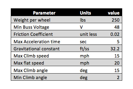
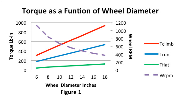
Three conditions will be looked at in this analysis. The first condition will be accelerating up to 75% of the maximum speed up the maximum incline. The second condition is for the cart accelerating on a 2 degree incline to maximum speed. The third condition is running at the maximum speed on the 2 degree slope. The 2 degree incline is used since most flat surfaces are not entirely flat. The power needed will be a function of the forces required using the parameters of the cart accelerating and running on a surface. The power to accelerate up the 15 degree slope calculates to 3000 watts, the power to accelerate up the 2 degree slope calculates to 1800 watts, and the power to run on the 2 degree slope calculates to 400 watts. There is a large range in power and the minimum running power on a flat surface will be very small. It is hard to come up with an average power since all operating conditions will be different. The best solution for an average power is to set up a test run to get a consistent value. Since power is also a function of speed multiplied by torque, the torques required will change as the wheel diameter changes so that the power can stay constant. Figure 1 will show the torques for the three conditions as a function of the wheel diameter. As we would expect the torque required will increase as the wheel diameter increases. We will pick a wheel diameter of 12 inches and a motor outside diameter of 10 inches for the rest of the example.
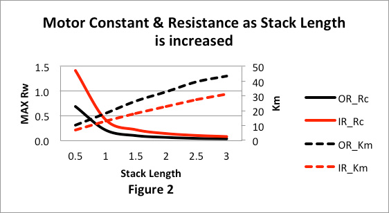
Now that we have a wheel diameter and motor diameter picked, we now need to determine a minimum motor length to get the power needed. The outer rotation and inner rotation motors we both compared as a function of the winding stack length. Figure two shows the motor constant and resistance of both styles of motor as a function of the motor stack length. We determined earlier that the maximum stator resistance was 0.18 ohms. We can meet this value with a stack length of 1.5 inches in the outer rotation style motor using bonded neodymium magnets. The outer rotation motor will need a 2 inch stack length even though it is using the stronger sintered neodymium magnet material. Another factor is the motor constant which is a measure of the motors thermal capacity. The units of the motor constant are torque divided by the square root of dissipated power. Figure 2 also shows that the outer rotation motor will have a higher thermal capacity than the inner rotation motor. This is not a big advantage since the inner rotation motor will have the winding attached to the motor outer diameter and will have a better thermal path to get heat out of the winding.
This analysis showed that the outer rotation motor gave a simpler design in that the tire was part of the motor and the motor could have a shorter stack than the inner rotation style motor that needed a longer stack and a separate wheel and tire. The shorter length of the magnet and stator used in the outer rotation motor would reduce the cost of the copper and magnet used in this design. This analysis was based on an airgap flux density of 5.5 KG for the outer rotation motor using bonded neodymium magnets and an air gap flux density of 8 KG in the inner rotation motor using sintered neodymium magnets. These results would change as other magnet grades are used which give different airgap flux densities but the results still would be similar to this example. There was not a large difference in the performance of the two designs and if other factors could favor one design over the other design, it would not be a major problem. Since the outer rotation motor is using a less expensive magnet material there would not be a large change in the costs of the two designs. It would still be feasible for a design to use either style motor. The motor constant was increasing with stack length in both of these motor thru the diameter range picked. This would mean that longer stack lengths would give a more efficient motor as the stack length is increased but the motor cost would also increase.