An IEEE study in 2008 concluded that 60% of electrical energy in the United States is used to run motors, the vast majority of which are induction motors running directly on the grid. Historically, the use of the electrical grid to directly provide motion was the killer app of AC power distribution, arguably more than illumination, which today accounts for around 30% of US electrical use. Compared to the steam engine, the relatively high efficiency and low maintenance of the induction motor ushered in a new age.
However, times have changed. Energy in general and electrical energy in particular is now viewed as a precious resource. The incremental cost of increasing the electrical energy supply is increasing. In fact, the cheapest generator a utility can build is the one that doesn’t have to be built at all because of increased energy efficiency.
The same 2008 IEEE study concluded that most electric motors in the U.S ran at 60% to 70% efficiency. This is in part a reflection of the acquisition economics of motor purchasing that favored low purchase price over lifetime running costs, favoring inexpensive low efficiency motors, even though the purchase price of a motor can be as low as 2% of the total lifetime cost. Other factors are the design practices of applying AC induction motors that have persisted for over a century. Since induction motor speed is set by the frequency of the utility grid, induction motors run at nearly constant speed. Most applications, however, involved throttling fluid or gas which had to be accomplished by mechanical means downstream of the motor. Add to this to the nasty propensity of an overloaded, grid powered induction motor to stall, and most applications were designed to use only a fraction of the capacity of the motor. Since induction motors are most efficient at full load, the overall efficiency of the system was less than optimal.
Energy awareness has improved. Most users now acknowledge and can account for the lifetime cost of a motor. Also, the availability of variable frequency and field oriented drives, both of which can both control induction motor speed and improve motor efficiency, has improved the efficiency picture. The Energy Independence Act of 2008 virtually outlawed inefficient induction motors, effective at the end of 2010.
All of this helps. The OEM or user redesigning a system that previously would use a grid operated induction motor only, can now improve efficiency and take advantage of varying the motor speed in their system. However the design practice has evolved into researching catalogs and the internet to assemble a puzzle of motor, drive and mechanical interface, approaching each element somewhat independently.
There is another approach.
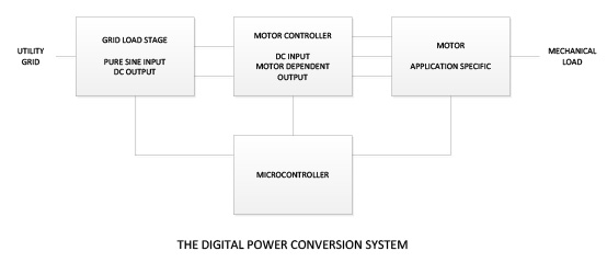
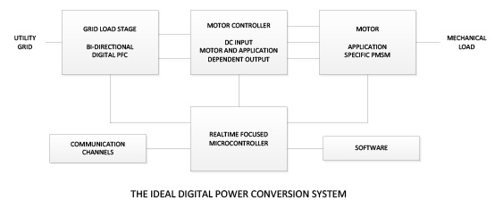
Throughout history we have developed the tools that allow us to take a fresh look at a problem. This is the case at the moment on the matter of efficient conversion of electrical energy to mechanical energy. If we stand back and approach the problem with a “clean sheet of paper” we see the task of a grid supplied controller is to match the sinusoidal utility voltage to the multi-phase sinusoidal load of the motor, with both ends operating at different frequencies and voltages. The task of the mechanical system is to convert the motors motion to air flow, fluid flow or other motion efficiently. Our “clean sheet of paper” approach is to configure each of these parts to operate together to achieve maximum efficiency, allowing tradeoffs between the elements as necessary.
Let’s look at the ideal for each system element.
The “Ideal” Grid Load
The most efficient load to the sinusoidal grid voltage is a simple resistor. All energy is efficiently converted to a load (in this case heat) and there are no harmonics or reactive currents to contend with. To the grid, that load is always present and always drawing a current proportional to the instantaneous voltage. When converting the AC grid voltage to DC, which we need to drive the motor inverter, this behavior can be mimicked by using a Power Factor Correction (PFC) stage. Since our generic motor load can provide regenerative power, our ideal PFC stage would be able to convert power in both directions; either from the AC grid to the DC bus or from the DC bus to the AC grid, always matching the sinusoidal waveform of the grid. The output of the PFC stage is a DC voltage. In theory, a PFC can produce any DC output voltage which can then be selected to be optimum for the motor. The presence of this DC bus on the output of the PFC stage decouples the grid from the motor drive electronics and the motor. They are only linked by the flow of power. The control electronics and motor can now be freely designed to maximize efficiency.
The “Ideal Motor
We can now jump to the output side of the system and determine the best motor to drive the application. Since our ideal controller (next section) will be designed specifically to match the DC bus to the motor, our ideal motor design can be driven entirely by the application. Because of its relatively rigorous design requirements, the induction motor does not lend itself well to the required design flexibility. The permanent magnet synchronous motor, however, is perfectly suited to a flexible design approach. All that has to be maintained is the relationship between the permanent magnet flux path and the stator winding. The motor itself can be a conventional stator outside/ rotor inside design or an “inside out” (outside rotor) design. It can have any even number of poles. With more poles, the magnets can be formed from lower energy, less expensive and more available materials. The motor form factor can be long and skinny, short and fat, or even linear to fit varying packaging requirements. Since the magnetic gap on a permanent magnet synchronous motor is larger than that of an induction motor, the rotor and stator could be in different environments, as long as the material in the gap is nonmagnetic, such as stainless steel.
If we truly allow the design of the motor to best match the end mechanical load requirements, the electrical parameters of the motor can be all over the map. For example, a motor for a handheld polisher would want to spin at a high speed, keeping overall motor torque and weight low. The electrical parameters for such a motor would be low voltage constant (Ke) and low inductance. At the other extreme, a motor for a slow speed direct drive agitator would have a high Ke and high inductance. Since efficiency drops and the cost and size of components rise as current increases, the optimal motor voltage can be selected to keep currents and motor losses low.
The Ideal Motor Controller
Now we come to the motor controller. Since we are taking a “clean sheet of paper” system approach to the design, the only energy efficiency requirements for the controller are that it matches the DC bus voltage to the motor stator requirements. From the previous section, we see that a motor optimally designed to a load can have a wide variety of electrical parameters. One style controller does not fit all. However there is common ground. To produce smooth motion, the motor stator voltage will be multi-phase, most likely 3 phase, so the controller electrical topology will be that of a three phase bridge. What will vary with application is the scaling of the bridge to the right voltage and current and the switching pattern of the three phases.
Creating a wide variety of switching patterns is what modern microcontrollers do very well. A microcontroller can drive every switching device in the motor controller and the PFC stage with a signal coordinated with every other power handling device in the system. The exact optimum pattern depends on the application, is realized in software and can change with system operating conditions. For example, a high speed direct drive pump may have a relatively low motor constant (Ke) and inductance. We may design the software to have the PFC stage produce a variable DC bus and have the motor controller simply electronically commutate the motor.
Modern microcontrollers also bring communication to every application. Communication has been important to industrial drives for years, but now it is practical to add communication to the simplest of applications. Higher level management can now have visibility to every fan or pump for control and diagnostic functions. Eventually, “Smart Grid” standards will emerge, but there is no need to wait for them before taking advantage of this capability.
Once we have the ideal PFC, controller and motor, we can package them to better fit the system requirements. Conventional drives often require an external enclosure, remote from the controlled motor. With the system approach, we are free to explore options such as having the control integral to the motor or of having a single PFC section provide power to several motors and power supplies to run ancillary equipment.
The System
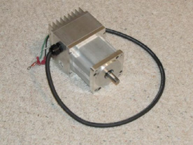
An Application Specific motor system
Courtesy Tru Tech Specialty Motors and Software Defined Power
The system approach looks at the complete system, from the utility source to the motor shaft and the production volume point where this becomes practical has been falling. Each part of the system can be crafted to meet specific criteria, such as size, cost and performance. Much like an architect draws on a portfolio for design concepts that he alters to the application at hand, we now have a portfolio of power conversion technologies, hardware designs, modular software and flexible motor design tools to execute a application specific system design at a reasonable non-recurring engineering cost. The result is not only a system that is cost competitive to the internet catalog puzzle approach, but a system that is more efficient, lower maintenance and more operationally flexible.