Design Challenges in Low Voltage, High Speed Permanent Magnet Motor Design
Designing a low voltage, high speed permanent magnet motor requires balancing electrical limitations with performance demands. In many renewable and off-grid systems, voltage is constrained, yet speed and torque requirements remain high. The result is a set of interconnected design challenges that need to be addressed at both motor and drive level.
These applications typically involve:
- Battery-powered permanent magnet motor systems operating from 12V to 48V
- Renewable energy sources such as solar panels or wind generators
- Remote or off-grid installations with regulated or fluctuating voltage input
- Operating speeds in the 4,000 to 5,000 RPM range
Under these conditions, several electrical effects dominate system behavior:
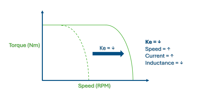
- Low motor voltage constant (Ke), which reduces torque constant (Kt)
- Low inductance permanent magnet motors that produce higher current ripple
- Elevated current demand to generate required torque
- Increased I·R losses and thermal stress
Although higher voltages would allow a higher Ke and greater winding inductance, many real-world systems have to operate within strict low-voltage constraints. This article examines the electrical tradeoffs inherent in low voltage, high speed permanent magnet motor design and explores practical approaches to improving motor drive optimization in these environments.
Understanding Motor Voltage Constant (Ke) and Torque Constant (Kt) in High Speed Applications
In low voltage, high speed motor applications, the relationship between motor voltage constant (Ke) and torque constant (Kt) becomes critical. Because torque constant is directly linked to Ke, a reduction in voltage constant forces higher current demand. This creates efficiency challenges in torque constant high speed motor applications where resistive losses escalate quickly.
Motor Ke is the quotient of voltage divided by the speed in revolutions per minute (RPM). The equation for motor speed is derived from the voltage equation for a motor, (V=I*R + Ke*S + L*di/dt). The inductive term for the voltage is usually a small number and can usually be ignored when using this equation to determine a starting value for the Ke needed. Even in low voltage situations the turns count will be small allowing it to be ignored in most cases since the inductance is a function of the turns and is also very low. This term in a very low voltage case does need to be checked because if the current ripple di/dt is large the voltage loss can still be large when compared to the very low input voltage.
Motor Ke is the quotient of voltage divided by the speed in RPM. The motor torque constant can be shown to be equal to the motor voltage constant in the MKS set of units and is expressed as N-M/amp, ( Ke = V/S = B*L*N = T/I = Kt). This means that the torque constant will also be low and the motor will require large currents to produce the torque required in most applications.
- The other factors in the above equation are winding length L in meters and air gap Flux density B in Tesla.
- The N in the above equation is the number of conductors in the winding.
The length is optional since the motor in these types of applications are not a typical application issue in most cases. A shorter length would give a lower resistance and inductance. The longer length would have a higher resistance and inductance but will give higher rotational losses. Since the torque constant is equal to the Ke and will also be low, the current required in these applications can be a very high number. This high current will give a high I*R voltage drop and leave less voltage available to generate the speed desired. This means that an even lower Ke will be needed. This requires more current and a runaway condition can develop. This lower Kt will also require more current which will drop the voltage even lower because of the increasing I*R voltage. This could lead to a runaway condition. Failure to consider this would give lower speeds than desired. Another problem with the low Kt is that a higher amount of current is needed to overcome the torque losses due to friction and the rotational losses. This adds to the voltage lost in the I*R drop and makes the Ke needed a little lower than expected. The current capacity of the wires in the motor winding will also need to be considered since they could go into a fuse condition if they cannot carry the current needed.
Motor Topologies and Their Impact on Inductance and Resistance
The physical construction of a permanent magnet motor directly influences inductance, resistance, and current behavior. In low inductance permanent magnet motors, pole count and geometry determine how the system responds under PWM switching. Selecting the right topology is central to improving stability in low voltage motor systems.
The most common type of design is a cylindrical type of motor. This motor has a long length when compared to the motor diameter. Due to the small diameter the number of poles will be limited. This will result in a trend to a higher value of the resistance and inductance. This style motor will tend to be a high speed type of motor and are commonly used in geared type applications.
Another style of motor is commonly called a pancake motor. These motors tend to be large in diameter and the length is significantly shorter than the diameter. These motors tend to have a large number of magnetic poles and will have very low inductances and resistance. This will mean that these motors will be low speed and can be used in direct drive applications. The pancake motor can also easily be made into an outer rotation type of motor with the magnets in the outer rotating cup. This style motor will have a high inertia and would be used on directly coupled high inertia loads. When the smaller pancake motors are used, the high pole counts will give a low inductance and can give problems due to the high ripple currents.
Another class of motors would be the axial flux style motors. These motors would also mainly be a pancake style motor but use powdered metal instead of laminations. These motors can be made with either rotating iron or rotating coils and will have a large variation in inductance in these different construction styles. Inductance will vary inversely with the number of magnetic poles of the motor. This function of increasing inductance with increasing pole count is proportional with the square of the number of poles.
Another effect of the higher pole count is the commutation frequency. The higher the speed of the motor the higher the frequency of the commutation switching of the motor phases will be required. The lower inductance and resistance will give a lower electrical time constant which allows a faster rise time of the current in the PWM switching. The higher pole counts will require a higher PWM frequency to get several current pulses in each commutation cycle. The higher frequency gives a benefit in that it will minimize the current ripple amplitude and lower the resistive heating in the stator. The negative effect of the higher frequency required for higher pole counts is that the eddy current losses and the hysteresis losses increase with frequency so these losses will be higher. These factors will result in a higher motor temperature and lower motor efficiency.
Magnet Material Selection and Its Effect on Inductance
Magnet material selection plays a significant role in managing inductance in low voltage, high speed motor designs. Adjusting magnetic energy levels affects winding turns, resistance, and thermal performance. This becomes especially important in renewable energy systems where efficiency and heat management are tightly constrained.
Another way to change the motor inductance is to change the magnet material used in the motor. The motor voltage constant required, Ke, is defined by the speed needed and the voltage available for the application. Since the Ke and the motor torque constant (kT) are dependent on the Flux density of the air gap, the flux density in the airgap will affect the resistance and inductance. A 4 inch motor design was used to check the effects of the magnet material. The Ke used in this comparison was 8 v/krpm.
The stator lamination was varied in both the tooth width and the back iron width to keep the Flux density of the lamination tooth at 14 KG and the back iron flux density at 13 KG. This will allow the slot area to change for each magnet material and then the number of winding turns was changed for each material to keep the Ke constant.
The magnet thickness is less for the high energy material so the actual volume of the magnet will change. The lower energy magnet material will usually cost less so this will offset the increase of the volume of the low energy material.
Current Ripple in Low Voltage Motor Systems
Current ripple is one of the most significant challenges in low inductance permanent magnet motors. In low voltage motor systems, rapid current rise and fall times amplify ripple amplitude, increasing copper and magnetic losses. Managing current ripple in low voltage motor systems is essential for maintaining efficiency and thermal stability.
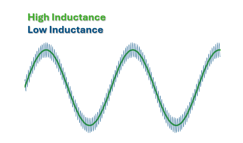
Current ripple is the major system level problem due to the low inductance. The low inductance will give a higher rise times and fall times of the current ripple due to the PWM frequency switching the phase currents. This will result in a higher peak to peak value of the ripple current. Since the positive side of the average current will produce a positive torque ripple and the negative side of the average of the current will give a negative torque ripple, they balance out with no net torque change. This ripple produces heating in the winding and reduces motor performance due to the added copper losses and magnetic losses. Increasing the frequency of the PWM is a common way to try to reduce these losses. The increase in frequency will result in a shorter time for the rise and fall of the current ripple and reduce the current ripple amplitude in this way. This does reduce the copper losses but will increase the iron losses. Both the eddy current losses and the hysteresis losses increase with the switching frequency so these losses will be higher. The lamination thickness and material can be changed to minimize these losses but this can also affect the lamination cost.
Motor Drive Optimization for Low Voltage Motors
Standard catalog components often struggle in low voltage, high speed environments. Effective motor drive optimization for low voltage motors requires programmable, real-time control and system-level coordination between motor and drive. Digital drives now allow fine tuning to address inductance, ripple, and voltage variation dynamically.
One trend that has become common is to shop for motors and drives through a catalog. If the components chosen don’t meet the requirements the system will run hot, become inefficient, and give premature system failures. If the system is oversized to allow all components to exceed the minimum requirements, then the cost will be high and the system components will also become inefficient and be larger than needed. This type of system will also tend to need to be degraded in the voltage and current from the levels available. Any of these motor drives are now digital type drives that can easily be programmed to match more applications. This will help in getting a drive that better matches the application requirements. These drives can have the same basic hardware and be programmed to match the parameters of the motor requirements to meet the application requirement. These programmable drives can also react very fast to feedback from the motor and the load to define the optimum inputs to the motor. The real time response of these systems will allow the system to operate at a higher efficiency level and at a lower power level to meet the real time requirements of the total system. Since everything is in real time the system can be programmed to react to issues due to low inductance and minimize the negative effects of low inductance and low resistance. Also since the drives are digital in nature, various algorithms can be used to minimize the effects of inductance and current ripple.
Custom Motor and Drive Systems for Renewable and Battery Applications
In renewable energy and battery-powered applications, fully integrated motor and drive design delivers the highest efficiency. Custom motor and drive systems for renewable energy sources such as solar and wind must accommodate voltage variability while maximizing output. Tailoring both components together reduces inductance-related inefficiencies and improves system performance in 12V–48V battery-powered permanent magnet motor systems.
The systems using programmable drives can be taken one step further by designing a motor and a drive specifically to meet the requirements of the application. If the actual application can be defined a motor and drive system can be designed to meet the application and give a more efficient and less costly solution to the problem. This would allow the motor to be designed using the best magnet materials and magnetic design that can be used for the application. This drive system can then be programmed to give the best voltage and current to the motor by modifying the input voltage and current provided to the system. This would be monitored with feedback from all components to the drive to match the most efficient output of the system using the input power that is available at real time. The voltage delivered to the motor can also be varied by using digital voltage level shifting to get the best available power to the motor and the best available power to the load. Since this is all done in real time, these changes can be made to match the real time requirements. This system could also change the frequency in real time to minimize current ripple when it can be allowed. Knowing the real time condition of the input power and the output power allows many reactions to this in the programmable portion of the drive. This system would only be limited by the amount of feedback from the input and output of the system. This type of system can use a varying type of input power directly or run off batteries and match the input power to the output power. This system can change system parameters to meet the needs of the motor used. A motor then can be designed with any available magnet material and any pole count that will work best for the total application. This would greatly diminish the effects of the inductance and maximize the efficiency of the motor.
Optimizing Efficiency in Low Voltage, High Speed Permanent Magnet Motor Systems
In low voltage, high speed applications, the physics can’t be ignored, but they can be engineered around. Inductance, current ripple, thermal behavior, and efficiency are not independent problems; they’re consequences of design decisions made at the motor and drive level.
When those decisions are approached holistically rather than piecemeal, low-voltage systems can achieve stable, efficient performance even under demanding operating conditions. If you’re developing a 12V–48V renewable or battery-powered application and need a motor solution built around your exact constraints, contact TruTech Motors to discuss a custom-engineered system.