TruTech Servo Motors & Systems
Electric motors have had use in agriculture type applications for many years. These applications have tended to be belt driven types with electric motors capable of only one speed. Any change in speed required needed to have the gear ratio changed. This has required other methods of controlling the output of the equipment using electrical motors. This added equipment has been baffles in air movement applications, valves in fluid applications and other devices to limit the system output. These added devices cause a large decrease in the efficiency of the system. There are two methods of achieving this speed control. One would be to simply change AC motor to a motor with speed control. A better method is to use a direct dive coupling between the motor and load. The major improvement of this type of a direct drive system is that the motor can be used as a direct drive between the motor and load which will eliminate the gearing system and load decreasing systems needed in the AC motor systems. This system will also be more reliable since the direct drive will eliminate belt wear and replacement. Many of these loads are of a high inertia type and are better matched to a motor with a high inertia. This paper will discuss the use of outer rotation direct drive permanent magnet motors in agriculture type applications.
The most common type of agricultural application would use an AC motor connected directly to the power grid though a line voltage and require a belt, chain or gearbox to connect the motor to the load at the reduced speed that would be required by the load. There would also be a system of baffles or valves to control the output. This load control could be achieved by speed changes to the load to control the output. A direct drive system would be a system that has a larger motor coupled directly to the load. This system eliminates the need for the gearing systems. Speed and torque control can be obtained by using variable frequency AC drive but another approach is to use permanent magnet servo motors. The direct drive system will need a motor controller which is an added cost over the line driven AC motor system. This cost will be offset by the elimination of the gearing components of the direct drive system. The costs of electronic systems to drive a permanent magnet brushless motors has been greatly reduced and are no longer a high cost adder to the system and would not be a large factor in the total system cost. A major cost savings of this approach will be the elimination of the gearing such as the pulleys and belt system including the pillow block that would be coupled to the load or in other cases eliminating the gearbox. Another major cost savings will be in the improvements in efficiency due to the ability of the system to change motor speeds to match the output required from the system instead of using baffles and valves to control the output. The direct drive type of brushless motor would have two possible types of construction. One type would be a conventional inner rotating rotor with a wound stator in the motor housing. This motor would use a permanent magnet rotor that would be mounted directly to the fan hub used on the present agricultural motor applications. The other style would have the rotor shaped as a cup with the magnets rotating outside of the stator. There would be two major advantages to the system using the permanent magnet brushless motor. One would be that the brushless motor and controller could have the speed controlled at RPM’s low enough to function as direct drive to the load. This would eliminate the pulleys, pillow blocks, and the belt to drive the load. This would give a higher efficiency with the losses of the belt drive and pillow block assembly eliminated.
The agricultural type applications that would use smaller direct drive electric motors could be used are mainly in the areas of animal husbandry. This is usually a remote location with buildings to house animals and the buildings and equipment to handle the feed and water for the animals. One application that would be best served by the outer rotation motor would be the ventilation fans on the livestock buildings. These are currently fans driven by an AC motor coupled to the fan using pulleys belts and pillow blocks. Present systems will rely on external baffles or to control and reduce the output while the motor is always producing the maximum power required by the load. Another type of high inertia load application would be pumps to move water to the animals. This application would typically be a motor coupled to the pump by a gearbox. Here the pump could be integrated with the motor rotor. These types of applications would run at low speeds at the load. The permanent magnet brushless motor can run at these low speeds at high efficiency levels. This high efficiency range will extend though a large range in speed giving the ability to vary speed as the load requirement changes to eliminate the need for the control baffles and valves. The brushless motor will be able to reduce the motor output when the load requirements are reduced and this will also reduce the power input to the motor. This will reduce input power requirements from the power grid and move the agricultural applications into the green energy terminology. The permanent magnet brushless motor will also have a significantly higher efficiency than most common AC motors. The permanent magnets will replace the rotor winding or squirrel cage rotor and eliminate the losses in the rotor. Since this motor is also rotating at a lower RPM the iron and speed dependent losses will be reduced. The full result of the brushless motor will be efficiency improvements in the three areas of reducing copper losses, iron losses and speed dependent losses. Another similar application would be in grain movement and mixing. This would tend to be augers for grain movement and belt applications for feed mixing to control the feed mixture by the speeds of the belts. These applications could either be met by inner rotation motors or outer rotation motors.
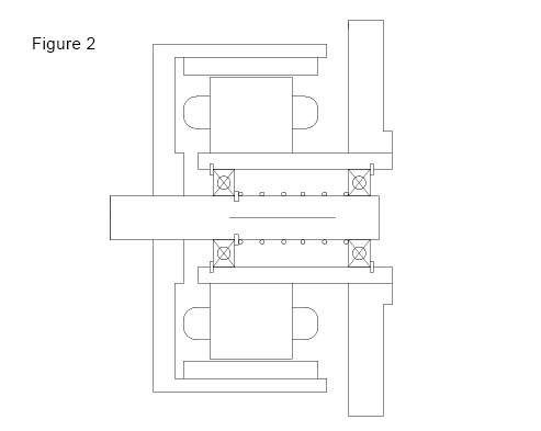
These agricultural applications tend to have a high inertia type load that needs to maintain the torque required with little speed variation. The outer rotation style rotor has the advantage that the rotor will have a large inertia, which combined with the high load inertia, will give a very even speed with little instantaneous velocity control. The only real velocity control would be to maintain the output overall average output speed changes as the load conditions change. The fact that the magnets are outside of the winding will allow a lower energy type magnet material and a larger magnet volume for the magnet. This will allow a lower energy magnet such a ferrite magnet material which will reduce cost. This will result in a larger volume for the motor but most of these applications would not be size restricted. It should be mentioned that the direct drive motor will require a larger motor to produce a larger torque since gearing is not used. Again this is not a problem since size is not a major constraint and the higher efficiency is the real benefit that is desired. The area of the winding is inside of the magnets which are very similar in style to a brush type or a universal motor. This makes winding and assembly tooling readily available for this motor. Another feature of the outer rotation motor is that it tends to be a pancake style motor with a large diameter and a short length. This would not be a problem on fans and pumps since these have rotating parts with a large diameter. The short length is mainly due to the cup design of the rotor. The longer the motor is made the more unstable the rotor could become. Since this is a direct drive motor running at low speeds the balance and vibration is not as critical as on high speed motors. Figure 1 shows a view cut through the radial plane of the motor. The construction shown in this view is very similar to a brush motor and shows that tooling can be similar to a brush motor assembly for the winding and magnet structures. Figure 2 shows the axial cut view of the motor. This view will show that the construction of the motor assembly is very different than other motors. The rotating rotor portion is a cup shape with the shaft attached to the cup and would be the portion of the motor attached to the load. The base of the motor is the stationary part and is in the form of a T and would be the portion of the motor mounting to the frame of the equipment containing the load. The rotor can have both a shaft extension and mounting holes in the end of the cup. This would allow a load such as fan blades or pump vanes to be mounted directly to the rotor to eliminate coupling components. This view does not show a sealed motor. Most agricultural applications would require sealing. The method of sealing would change depending on the type of load and was not included in the view. The simplest type of sealing would be using a cup with a hole for the shaft extension with a shaft seal. This cup would fit over the rotating rotor and be sealed to the stationary motor mounting plate. Another cap would be needed to seal the opening for the bearings in the mounting plate.
Another large advantage of the Brushless motor system is that it can operate over a large range of input DC voltages to the motor controller. This would allow an agricultural fans and pumps and other loads to operate in a range from a 325 volt DC buss, from a 230 volt AC line, to a 12 volt DC buss from a battery. This would be accomplished so the same basic motor design could change from operating on line AC voltage to battery powered DC voltage with a winding change to the motor and minor changes to the controller. The controller could also use DC voltage conversion so the same motor could operate from both AC line input and battery power. This would allow the agricultural fans, pumps and other loads to be operated from solar panels on the roof of the building where they are used in or from a windmill located in the area of the buildings. This would require battery or capacitive type energy storage but would make the building or building complex self sufficient on energy requirements for the air movement portions. This would have an added advantage as an incentive to increase the areas of the green energy to all areas of the complex. The backup source could be either an efficient diesel or natural gas generator or the power from the small local fuel cell generators that are currently in development in several companies. The move to brushless direct drive motors would move the agricultural community into the so called green movement and encourage the development of other fuel sources. There are several possibilities for this alternate fuel development such a fuel from animal waste or from crop waste.
The change from the constant speed single or double speed motors operated from the power grid from distant power generation stations to local power systems to local power generation and more efficient motor load systems would give a major savings over the present system. These savings would be in both more efficient use of the energy in the motor systems at the site and that the energy can be generated locally instead of being transmitted over large distance with transmission losses. Using green energy sources is a common term but investigating ways to use this green energy in more efficient ways is also very important. Since a major portion of the generated electricity is used in motors, the motor and controller design is also very important to consider along with generating and conserving green energy. The costs of the systems will not be significantly different and the overall operating costs would be reduced. The direct drive brushless system will have a motor controller which will replace the gearbox or belt, pulley and pillow block shaft assembly. This will make a better efficiencies and cost reductions. The real cost savings of the brushless system will be in power consumed. Another possible savings would be in varying loads such as varying the speed of a fan to match the amount of air movement needed instead of running a motor at maximum output and limiting the air flow with baffles. The Current AC systems are not speed controlled and need to generate more than the minimum required so that they are capable of meeting the peak requirement conditions. Another large advantage to a local energy storage system is that any power required from the power grid could be sourced at times of low energy consumption on the grid and stored for use when the power grid energy is stressed by high consumption. The purpose of this paper is to show the benefits of the use of direct drive motors in agricultural applications using local stored energy to achieve better motor efficiency and eliminate the losses in the power transmission from distant power generation sources. While this is easy to understand another purpose of this paper is to show that another type of direct drive motor can fit the high inertia type loads and save more cost in eliminating the coupling requirements by coupling the load directly to the rotating portion of the motor.