The Case for Speed in Low-Voltage BLDC Motor Applications
An unmistakable trend in off grid motion control is the migration to electrical alternatives for existing mechanical, hydraulic and pneumatic systems. This was first evident in military aerospace applications, but has begun to permeate commercial applications like auxiliary vehicle equipment, solar, wind powered pumping and agriculture. By approaching the application from a system point of view, these systems can be simplified at the same time they're being made more efficient and intelligent. Designing a high-speed BLDC motor allows output power to be maintained while reducing torque requirements, enabling smaller and lighter systems.
Physics does impose a penalty for high electrical commutation speed, and that is a low voltage constant (Ke) and the resulting low inductance. Consider for a moment the wider scope of design configurations that would be possible if the system designer could disregard low inductance. On the high-speed horizon, unconventional applications such as inline hydraulic pumping become possible. On the low-speed, high pole count horizon, direct drive traction applications come to mind.
Why Conventional Drives Struggle With Low-Inductance BLDC Motors
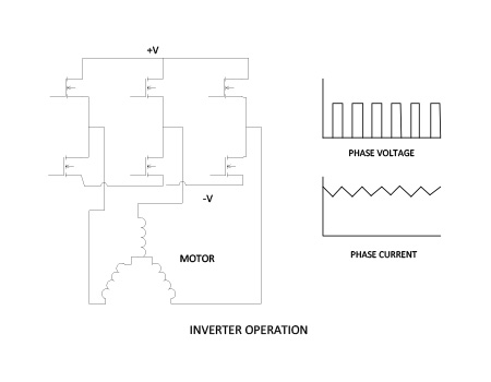
In a conventional inverter based motor drive, the impedance of the motor inductance is used as a low pass filter to produce a near constant current in the motor stator. The PWM voltage waveform from the inverter is applied to the motor. The resulting motor current has an AC component inversely proportional to the frequency of the inverter and the inductance of the motor stator.
Iripple = f(1/(freq * Lmotor))
This ripple current produces losses in the stator through three mechanisms. Eddy current losses and hysteresis losses occur in the laminations while the amplitude of the ripple current will cause I2R losses.
Designing the motor for a higher speed will lead to a lower Kt, less turns on the stator and less motor inductance. In order to keep ripple current low, the frequency of the inverter can be increased. However there is a practical limit for this. In a laminated stator, increasing current ripple frequency but keeping the ripple current magnitude level to limit I2R losses, will result in increased hysteresis and eddy current losses because a larger component of the ripple flux will circulate within the stator lams themselves. At the same time, a higher PWM frequency will result in higher switching losses in the inverter itself.
Another disadvantage of increasing the PWM frequency with a conventional inverter motor drive is an increased EMI footprint. All systems exhibit parasitic capacitance from the stator winding to the laminations. Increasing the PWM frequency will lower the impedance of the path and increase the high frequency leakage currents, increasing EMI.
A Two-Stage Controller Approach to Motor Voltage Regulation
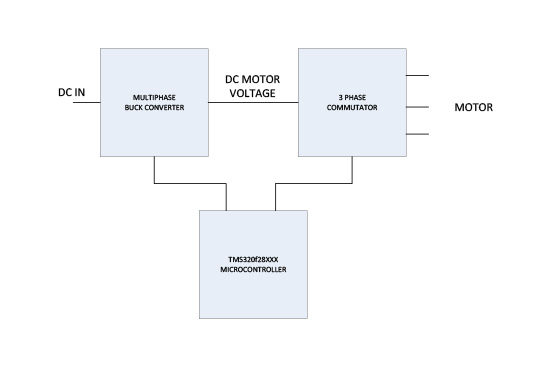
A solution to this paradox is the Two Stage Controller where the first stage uses high speed switching regulator techniques to regulate the motor voltage and the second stage only commutates the motor. This two-stage approach allows motor voltage regulation to be handled independently from commutation, improving efficiency and reducing losses in low-inductance BLDC systems.
Separating Voltage Regulation From Commutation in High-Speed BLDC Drives
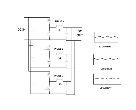
Our updated “chopper” is actually several MOSFET buck/boost converters operating in parallel, each phase shifted from the others in a multiphase configuration. This spreads the power over several power devices and provides lower stress on the individual components, particularly the input capacitors. By running the converter stages at 100Khz or higher, magnetics can be kept small and light,
The converter stage operates as a multiphase buck converter when the motor is operating as a motor and as a multiphase boost converter when the motor is operating as a generator.
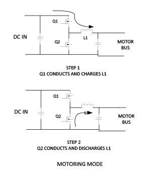
When motoring, MOSFET Q1 is turned on, charging inductor L1 with current flowing from left to right. Then Q1 turns off and MOSFET Q2 is turned on. MOSFETs can pass current in either direction, so the inductor current switches to Q2. At this point, the voltage across L1 is negative and the current begins to fall. Tuning off Q2 and turning on Q1 repeats the cycle, effectively pumping current into the output capacitor.
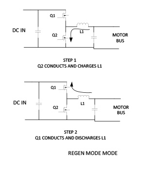
In generator mode, Q2 is turned on and inductor L1 is charged with an increasing current flowing from right to left. Then Q2 is turned off and Q1 turned on. Now the inductor current flows through Q1 into the input capacitor, producing negative power flow.
The input and outputs of the converter are both DC, with all the electrical switching carried out in the circuitry between the input and output capacitors. Careful and tight PCB layout is necessary to keep high frequency voltages and currents from getting into other equipment. In high-speed BLDC applications, separating voltage regulation from commutation helps reduce current ripple and EMI.
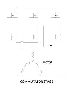
The commutator’s primary function is to steer the current from the first stage into the appropriate phases of the load motor. These devices run at the commutation frequency, typically a few thousand Hertz at the most. Switching losses are low and losses are dominated by conduction losses. One consequence of the switching at commutation frequency is that bootstrap biasing of the upper switches is problematic. At low speed, a bootstrap biasing scheme may not have enough bias voltage holding capacity to keep the upper inverter transistors on. This may be resolved with either dedicated DCDC converters or by an imposed, relatively low frequency, low duty cycle bias refresh using the lower switching device.
System-Level Design Considerations for Two-Stage BLDC Controllers
Looking back to the block diagram of the two stage controller, there are two DC links (the input and the motor voltage) and one AC link (the voltage to the motor phases). The DC links can be physically long and the buck and commutation power stages need not be in close proximity. If necessary, the commutation stage can be mounted directly on the motor and the buck stage can be remote, perhaps sharing space with operator controls and other power supplies. Also, in some systems, several motors can share a common DC link, although they would all be responding to the same, controlled bus voltage. This may be useful in some pumping or air handling applications such as driving several small agitator motors in a system that replaces pneumatic agitators.
Today the two stage controller can be driven by microcontrollers such as the Texas Instruments TMS320F28xxx series. These microcontrollers can generate high resolution PWM waveforms well above 100 kHz to efficiently drive the buck/boost phase as well as conveniently provide logic to the commutation stage.
Scaling the Two-Stage Architecture Across Power, Voltage and EMI Constraints
The two stage controller has a variety of design features that permit the concept to be scaled to a wide range of voltage and power levels.
By careful software design, most of the software functions required to implement the Two Stage Controller are invariant when scaling the system to other voltages and power levels. Some, like the software modules to instantiate a buck/boost phase, may simply be duplicated to expand the concept to 4, 6, 8 or more stages. Others, like commutation are invariant or may flexibly implement 120/60 degree trapezoid commutation or different pole counts and provide motor speed for an outer speed loop, which then controls the buck boost stage to maintain speed. This flexibility is particularly useful when supporting a high pole count BLDC motor without redesigning the control architecture.
This approach is particularly effective for low-speed, high-torque BLDC motor applications where mechanical reduction can be avoided.
At low voltages, high power means high current and current handling components are larger, harder to cool and system performance is more sensitive to voltage drops. A practical limit for low voltage systems is 100 amps of motor current. Beyond that, it can be more economical to raise the system operating voltage. Component wise, there is a practical limit for low voltage as well, and that is around 80 volts.
The next jump in voltage ratings is to 600 volts, to encompass utility sources between 90 and 260VAC. Some off grid power sources such as wind generators can produce this voltage range directly. Others, such as hybrid vehicles operate in this range as well. By scaling the components appropriately, the Two Stage Controller can be applied to driving low-inductance motors in these applications as well.
EMI is an important consideration in today’s power electronics. In addition to the federally mandated FCC requirements, there is the practical consideration that a large EMI footprint can negatively affect nearby equipment such as radio data links.
All electrically isolated electrical equipment exhibit a stray capacitance to ground. In a motor, the stray capacitance to ground can be particularly high because of the large, close surface areas of the stator windings, which are floating, and the stator, which is grounded. Any imbalanced voltage in the motor windings will appear across this capacitance and the resulting current can be conducted down the ground wire. In conventional inverter motor controls, as the modulation frequency is increased to reduce ripple current to drive a low inductance motor, the higher harmonics of the voltage waveform are more likely to be imbalanced. These high frequency voltages lead to high frequency ground currents. The ground conductor then becomes an antenna and radiates.
Another, more subtle EMI effect of driving a motor with high frequency PWM voltage, is that the rotor can itself be electrically isolated from both the stator and the windings, particularly when spinning at high-speed on good bearings. It then becomes a third plate in the winding/stator capacitor and picks up a voltage of its own. The bearing isolation is imperfect and the rotor would repeatedly short out to the stator. Every time this happens, current passes through the bearing. These currents can be high enough to pit the bearing and reduce its life.
The Two Stage Controller drive scheme can radically improve both these situations.
- First, the motor in the Two Stage Control system sees only the commutation frequency, reducing both the risk of voltage imbalance and currents through the parasitic winding/ stator capacitance. This can be further reduced by locating the commutation stage close, or even on the motor.
- Second, the buck/boost phases, which are running at high modulation frequencies, confine the high frequency voltages and currents to a small space where all aspects of the design can be controlled independent of the motor. Also, each phase carries 1/n of the total motor phase current, where n is the number of buck/boost phases. By selecting the number of phases to keep each phase current below 20 amps the EMI footprint is further reduced.
Proof of Concept: A 3 kW, 36 V Low-Voltage High-Speed BLDC Motor System
As a Proof of Concept, Software Defined Power worked with TruTech to design and build a prototype system of the Two Stage Controller and a representative low-voltage, high-speed, low-inductance BLDC motor.
The motor in our proof of concept had the following characteristics;
Ke = 8.6 V/KRPM
R = .005 OHM Line to Line
L = 2.7uH Line to Line
Operating this motor with a conventional inverter control would be an extreme challenge. At the 3KW output level, input current at 36 volts would be 83 amps. To maintain even a large 20% current ripple, a conventional controller would have to operate at 400 Khz. Motor losses, switching losses and EMI would pose a significant challenge.
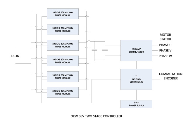
As mentioned, an input power of 3KW at 36 volts requires an input current of 84 amps. In order to minimize input current ripple, we chose a six phase buck/ boost configuration, with a 60 degree phase shift between them. A single phase, 20 amp 100 volt 100 KHz module was designed as a building block.
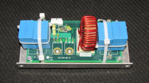
100KHZ 20 AMP 100V PHASE MODULE
A Texas Instrument TMS320F28335 Digital Signal Controller provides the PWM signal and the current control loop for each module, as well as providing the signals to a Powerex PM450CLA060 which served as a commutating inverter. A mosfet inverter would have been a lower loss choice, but our emphasis in this proof of concept was the buck/ boost stage. To allow operation over most of the input voltage range, the commutation stage was designed to operate up to 100% duty cycle. The buck boost stage was designed to operate up to 95% duty cycle.
Performance Results and Validation of the Two-Stage Controller
Tests were conducted with a 36V power supply and a test fixture to load the motor.
Test results of the Proof of Concept prototype showed good agreement with predicted results.
| TWO STAGE CONTROLLER TEST RESULTS | |||||
| INPUT VOLTAGE | INPUT CURRENT | INPUT POWER | DC LINK VOLTAGE | MOTOR SPEED | MOTOR CURRENT |
| 36 | 5.1 | 183.6 | 10.12 | 1000 | 20 |
| 36 | 10.5 | 378 | 10.44 | 1000 | 40 |
| 36 | 22.3 | 802.8 | 11.08 | 1000 | 80 |
| 36 | 9.4 | 338.4 | 18.72 | 2000 | 20 |
| 36 | 19.5 | 702 | 19.04 | 2000 | 40 |
| 36 | 39.5 | 1422 | 19.68 | 2000 | 80 |
| 36 | 13.5 | 486 | 27.32 | 3000 | 20 |
| 36 | 27.6 | 993.6 | 27.64 | 3000 | 40 |
| 36 | 56.5 | 2034 | 28.28 | 3000 | 80 |
| 36 | 17.2 | 619.2 | 34.2 | 3800 | 20 |
| 36 | 35 | 1260 | 34.52 | 3800 | 40 |
| 36 | 78.1 | 2811.6 | 35.288 | 3800 | 88 |
Voltage ripple on the DC link was less than 1 volt.
This configuration of the Two Stage Controller validated the concept and produced a number of useful building blocks for scaling to other applications, specifically software. For power electronics, cost and size decreases and efficiency increases with increased operating voltage. We are now in the process of scaling up the Two Stage Controller to 400 volts. This configuration uses only three phases in the buck/ boosts stage and a 30 amp Infineon power module for commutation and is pictured below.
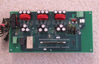
400V 15 AMP TWO STAGE CONTROLLER