Let’s be real: electricity is expensive and the tolerance for waste these days is low. Efficiency standards have tightened, even with motors accounting for a significant share of global electrical use. Estimates from CLASP show that motor-driven systems represent about 30 percent of total worldwide electricity consumption. With that scale of impact, the way we design motion systems matters.
For decades, a standard induction motor with a simple control scheme was considered “good enough.” That said, it ran directly on grid frequency and often delivered poor system efficiency when paired with mechanical throttling devices.
Modern applications need more. They need motion systems built around how energy actually moves through the machine.
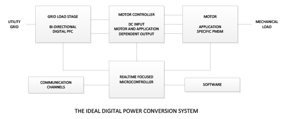
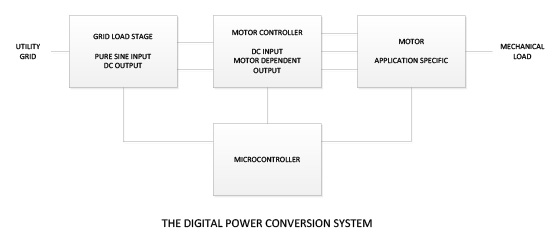
A full system approach to motor design begins with treating the power source, the conditioning stage, the motor architecture and the control strategy as parts of one solution. This creates room for higher efficiency electric motor design and better long-term performance.
From Components to Connection: A New Narrative for Motor-Driven
Think of the evolution in three acts:
Act 1: The Traditional Era
Induction motors dominated because they were simple, inexpensive and ran directly from the AC grid. Speed was fixed by line frequency. Most processes controlled flow or pressure with mechanical throttling. This pushed motors far below optimal loading and caused large efficiency losses. An overloaded induction motor also tended to stall, which led designers to oversize equipment and accept further inefficiency.
Act 2: The Cost-Awareness Era
As energy costs climbed and regulation stiffened, designers began to choose premium motors, add variable-speed drives (VSDs) and apply incremental improvements. But in many cases the architecture remained boxed: grid → motor → machine. Optimization was local rather than systemic.
Act 3: The Integrated, Future-Ready Era
Now, the most forward-thinking OEMs and system designers are adopting a full system approach to motor design. They view grid interface, PFC, DC bus, motor topology, controller firmware, communications and mechanical interface as one platform. They ask not just “Which motor do we buy?” but “What system shall we build around the motor to unlock new capabilities and future-proof flexibility?”
The Four Pillars of a Future-Ready Motor System
Here are the key areas that define a modern, future-ready motion system.
1. High-Efficiency Electric Motor Design
Permanent magnet synchronous motors allow designers to control speed, torque and electrical behavior through winding and magnet configuration. Unlike induction motors, PMSMs are not tied to grid frequency. Their Ke and inductance values can be shaped to match actual load profiles. This allows:
- higher speeds without excessive current
- higher torque without oversizing
- form factors that support unusual packaging
This flexibility is the foundation of modern high-efficiency electric motor design.
2. PFC Power Factor Correction Motor and Grid Interface
The way power enters the system shapes everything that follows. A PFC power factor correction motor front end can smooth the load on the grid, manage regeneration and create a stable DC bus. With that foundation in place, the motor and drive can operate much closer to their ideal performance range.
3. Energy Efficient Electric Motor Design at the System Level
Efficiency depends on how electrical and mechanical elements work together under real loads. A system-level design considers:
- drive behavior
- winding characteristics
- feedback devices
- gearing or direct-drive choices
- expected inertia mismatch
- environmental constraints
Selecting components separately often introduces bottlenecks, but designing them together allows the motor to use current more effectively.
4. Full System Approach to Motor Design
A full system approach shapes the power electronics, motor and controls as one coordinated design, which helps reduce overall system size and improve thermal behavior while lowering energy use. It also creates room for integrated electronics and makes it possible to build sealed, application-specific motion systems that match the environment instead of forcing designs into standard frames.

Why TruTech Leads the Way
TruTech focuses on designing motors and systems that match the real demands of a machine, not whatever happens to be available in a catalog. We develop PMSM motors and integrated controls that are tailored to the electrical, mechanical and environmental demands of each machine, helping OEMs achieve more consistent performance.
TruTech helps OEMs shape the motor and electronics around the machine’s real requirements. That produces more predictable performance and avoids the limits that show up when a motor is chosen before the rest of the system is understood. Because meeting the minimum isn’t enough anymore.
Accelerate Your Path
Download our comprehensive guide “Optimizing Servo Motors for Increased Machine Performance” to deepen your understanding of system-level motor design: design criteria, case studies, motor vs. torque/speed curves, tailoring techniques, and more.

