Custom Servo Motor Design and Optimization Solutions
Engineered for Performance, Designed for Value
Our design implementation process focuses on delivering the servo motor performance you need without overspending or underpromising. We start by understanding your system’s core requirements, then build a baseline design that includes exactly what’s needed — no more, no less. This method consistently helps reduce trade-offs between cost and performance, while aligning with best practices in manufacturability.
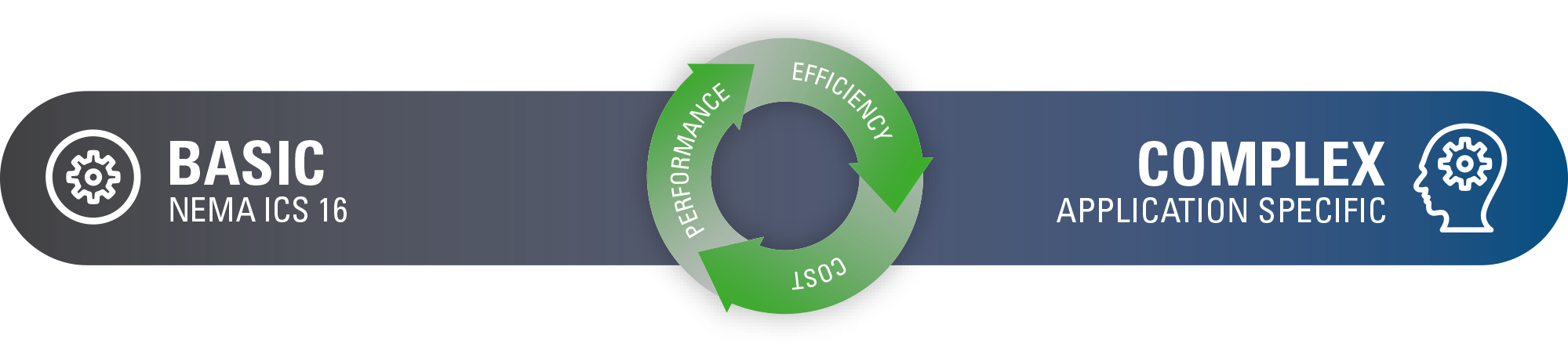
Whether your optimized servo motor relies on standard NEMA ICS 16 components or a fully custom configuration, our solutions are built to minimize cost without compromising reliability or results.
Permanent Magnet DC Servo Motor (PMSM) Solutions Built to Outperform
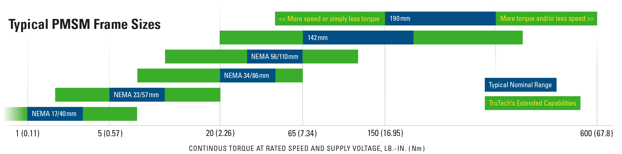
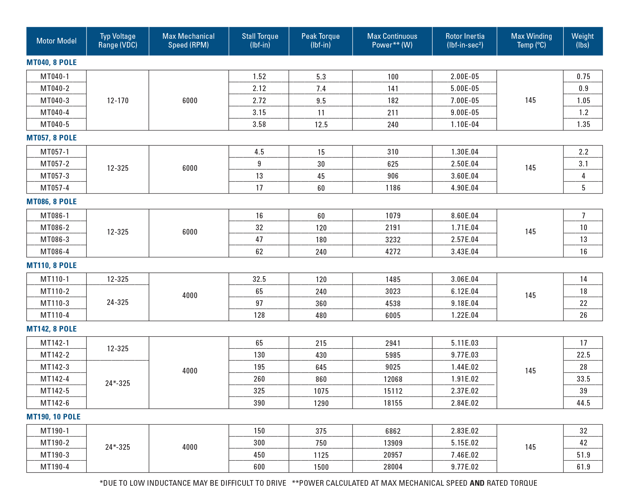
- Wide voltage range including low voltage options (10-80+ VDC) with high currents
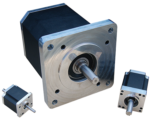
- Stocked components to NEMA ICS 16 dimensions along with IEC 142mm and 190mm metric sizes
- Continuous torques from 1.2-600 lb-in available for rapid prototyping
- Standard 416sst shafts, sleeved rotors
- Client specified Kt and Ke to torque and speed specifications
- Performance optimized
How Our Motors Work
Our Permanent Magnet DC Servo Motors (PMSM) start with motor components designed around popular NEMA ICS 16 standards coupled with windings to meet standard applications at low costs and short lead-times.
These motors are used for quick turnaround and rapid prototyping as components are available off-the-shelf.
Custom Servo Motor Solutions for Maximum Performance
While we offer standard servo motor options, our custom solutions are ideal when your application demands more precise performance. In advanced design phases, we optimize every aspect of motion, allowing nearly all motor parameters to be customized. That includes performance characteristics, physical sizing, output mounting, functional components and environmental considerations. Each element is tailored to meet the exact mechanical and operational requirements of your system.
Permanent Magnet DC Servo Motor (PMSM) Design Criteria and System Integration
When integrating a PMSM into a complete machine design, most motor parameters can be adjusted to match specific system requirements. A thoughtful, system-level design approach helps overcome common limitations and ensures the motor performs as needed within the full application. Once finalized, prototypes can be developed quickly, with production units available on a reliable timeline.
What Should You Consider When Designing a Custom Servo Motor?
Motor speed scales with applied voltage. If the required speed isn’t achievable at a given voltage, stator windings can be adjusted to meet the goal without compromising torque. This relationship is defined by the speed constant, Ke, measured in Volts/krpm, which can vary widely depending on design needs.
Motor torque increases with available current. If the required torque doesn’t match the available current, stator windings can be adjusted to deliver higher torque at lower current, with consideration for speed. This relationship is defined by the torque constant, Kt, measured in Nm/Amp. When more current is available and overall length isn’t a constraint, torque can also be increased by extending the stator or adding stacks while keeping the same frame size.
The nominal or expected supply voltage determines motor speed. Motor windings are designed with that voltage in mind. Because power electronics like servo drives are part of the system, the voltage seen by the motor is effectively DC, whether sourced directly from a DC supply or rectified from an AC line. Windings can be specified for any required voltage, including 10–80+ VDC for low-voltage systems, or common AC line voltages like 90, 120, 240, 480, or 525 VAC, and beyond. Understanding the supply voltage is critical to application success.
The rotor’s overall design determines its angular mass and the torque needed to achieve target acceleration and deceleration. Considering material selection and design details early in the process helps ensure proper load inertia matching. When inertia is mismatched, the momentum of the load can create performance issues.
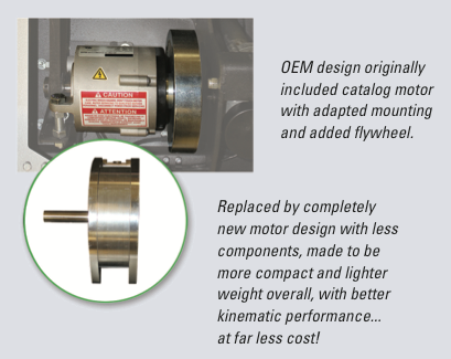
Frame size is typically driven by torque requirements. While standard sizes are available, they come with general housing constraints. When defining specifications for a given application, these constraints can be adjusted to find the best fit without needing to follow a standard size. Frame-less motors, which allow stators to become part of the machine frame, are also increasingly popular for reducing overall size and cost.
Ingress Protection (IP) ratings ensure the motor enclosure is properly sealed to meet application requirements. Higher protection levels involve more advanced sealing methods, which can be applied to both the housing and bearings as needed.
Standard mounting options are readily available but can be modified when additional requirements are needed. Avoiding a fixed mechanical interface allows for greater design flexibility.
Motor shafts are typically stainless steel, with standard interfaces available. However, materials and configurations can be customized based on application needs. These modifications may include changes in diameter, shape, keying and other features as required.
Housings are typically made from aluminum or powder-coated external laminations. Because motors may operate in a range of environmental conditions, it's important to review material options to match the application. Metals and coatings can be specified as needed to support expected use.
There are multiple options for terminating wiring to the motor. Standard components can be used, or both wire and connector types can be specified to suit the application.
When a motor is integrated into a larger assembly with components like gearing or actuation, the entire system can be designed as a standalone unit. This approach helps reduce both overall size and unit cost by creating a fully integrated, all-in-one component.
Brakes can be added to the motor system when needed, providing an optional component to support the specific requirements of the application.
A wide range of encoder devices are available and can be specified based on application needs. These are typically rear-mounted, and the rotor shaft and motor end cap can be modified as needed to fit the overall motor design.
Integrating drive electronics and digital networking into the motor is an ongoing trend in servo technology. This approach reduces both the number of machine components and overall wiring complexity. In the age of Industry 4.0, intelligent electronics built directly into the motor are becoming standard.
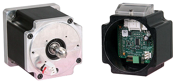
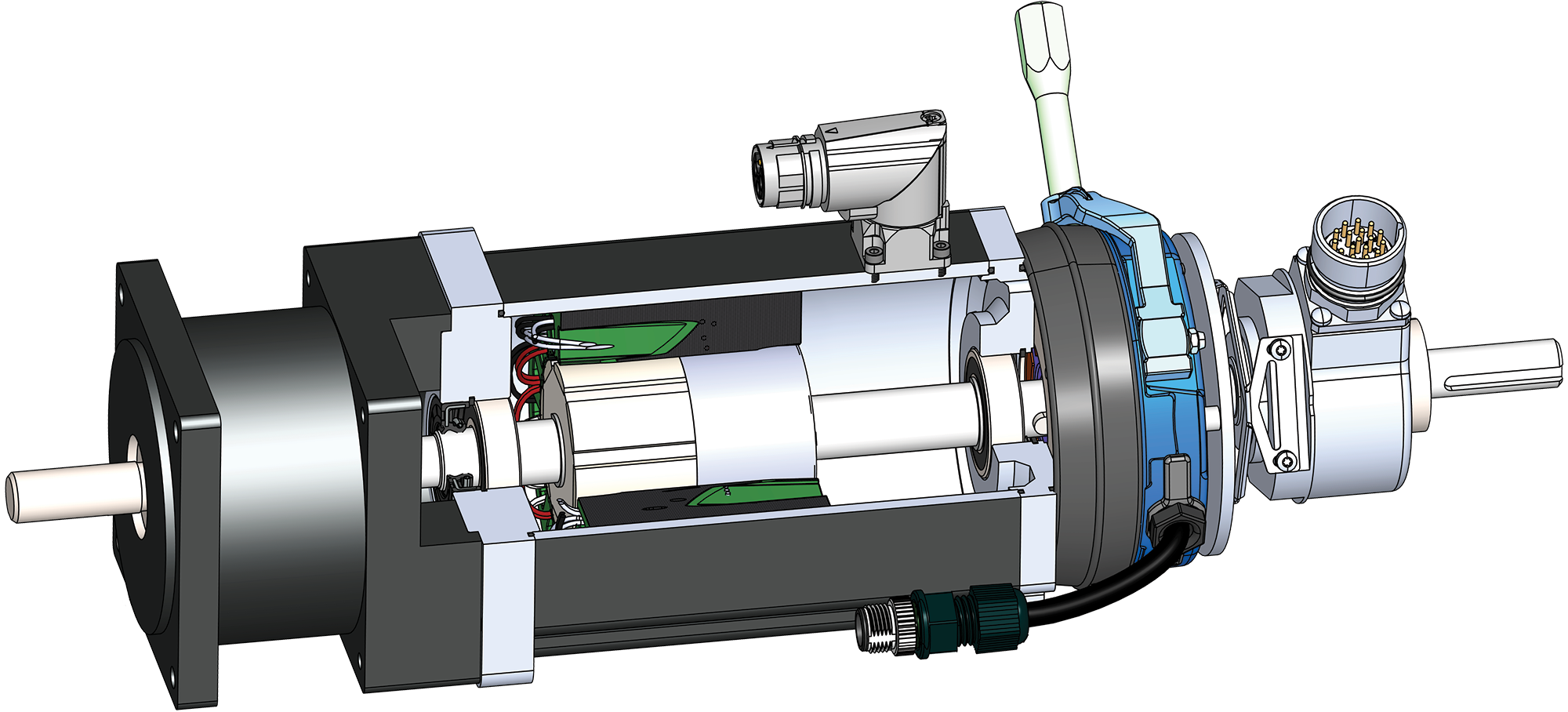
Complete servo motor assemblies can include the entire motion control system. The separated housing details both the motor, with end shaft magnet, and complete electronics sections. The compact end assembly houses the encoder, servo drive with internal motion control, external I/O and digital network communications for standalone capability and operation (courtesy of ADVANCED Motion Controls).
Want help designing a servo motor that meets your exact specs? Let’s talk about what your system needs.
Speed
The applied voltage to a motor is directly proportional to motor speed. Where higher or lower speeds are required, applied motor voltage may limit desired outcome. However, stator windings can easily be made to specifications that allow for increased or decreased speeds given the voltage requirement, with consideration for torque. This factor is called Ke and given in Volts/krpm and can have a wide range of possibilities.
Torque
Available current to a motor is directly proportional to motor torque. Where increased or decreased torque is needed, available current may not always be in line. As well with speed, the stator winding specification can easily be made to increase the torque for lowered available current, with consideration for speed. This factor is called Kt and given in Nm/Amp. Another option to increase torque, where plenty of current is available and overall length is not an issue, is to add to the stator length and/or number of stacks while retaining the frame size.
Voltage
The nominal or expected voltage sourced to the motor will determine the speed (see above). The windings in the motor are produced knowing that applied voltage. Since power electronics are in the system, i.e. servo drives, the resulting voltage the motor observes is considered DC, whether the power to the electronics is connected to a DC source or rectified DC from an AC line. Motor windings can therefore explicitly be specified for any voltage, including 10-80+ VDC for low voltage needs, typical: 90, 120, 240, 480, 525 VACs line sources or higher. Knowing supply voltage is critical to any application success.
Inertia
The overall design of the rotor results in the angular mass and determines needed torque while accommodating targeted acceleration/deceleration aspects. Considering in advance all aspects of design and materials, load inertia matching can be key specifications to a given application. Mismatches in inertia can be of large concern given overall momentum of the load.
Frame size
Sizing is typically predicated by the torque requirements. As standards are always available, so too come with them the general constraints of housing sizes. When defining specifications to any given application, these can readily be opened for ‘best fit’ considerations while not having to follow any ‘standard’ as desired for operation. As well, frame-less motors allow for stators to become a part of the machine frame itself and are increasingly popular while driving down overall costs/size.
IP rating
Ingress Protection ratings afford the application proper sealed motor enclosures as required. Increased protection comes with vastly improved sealing, and with multiple methods, for both the housing portions and bearings where required.
Mounting
Again, standards are readily available but can also be expanded where additional requirements may be desired. Not having to follow a pre-determined mechanical interface allows for increased options.
Shaft
Typically, these are stainless steel with available standards defining potential interface to the motor. However, multiple alterations of material and configuration can be specified as deemed necessary by the developer/application. This ranges widely and includes specifics for diameter differences, shape variations, keying, etc.
Housing Material
With housings typically made from aluminum, or powder coated external laminations, and the fact that they can see differing environmental conditions, dictates reviewing all types of variations to match application needs. Metals and coatings can be specified as required to match expected use.
Wiring/Connection
Multiple variations for termination of wiring to the motor can be made. Available components can readily be applied or, specifying both wire and connector types, can easily be adapted.
Gearbox/Actuator
As the motor itself becomes part of a larger assembly, incorporating other mechanical aspects such as gearing or actuation, the new ‘system’ can be made to stand alone. This further reduces size and unit costs to be inclusive as an ‘all-in-one’ component.
Brake
As another optional component to ensure proper application solution, adding brakes to a motor can easily be achieved where necessary and included as part of the motor system.
Feedback
Many market encoding devices are available and can be specified as required for the application. Usually rear mounted, this portion of the rotor’s shaft can be altered as needed and the end cap of the motor modified to fit overall motor design.
Electronics: Drives/Networks
Incorporating the drives power electronics and digital network is another trend in servo motor technology. This further reduces not only the number of machine components overall but also the complexity of the wiring. In the age of Industry 4.0, the ability to incorporate intelligent electronics in the motor is here to stay.